Download
1 / 15
160 likes | 432 Views
Enhanced Channel Model for HEW. Date: 2013-07-15. Authors:. This presentation proposes consideration of an enhanced 5GHz channel model for HEW, in particular, to target outdoor usage models, and system level simulations. Abstract.

E N D
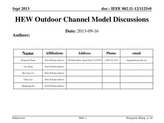
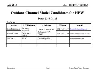
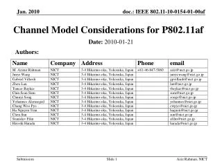
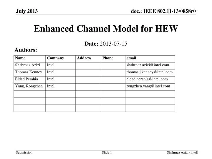
Enhanced Channel Model for HEW Date: 2013-07-15 Authors: Shahrnaz Azizi (Intel)
This presentation proposes consideration of an enhanced 5GHz channel model for HEW, in particular, to target outdoor usage models, and system level simulations. Abstract Shahrnaz Azizi (Intel)
The usage model environments presented in [1] address new and enhanced applications for HEW. • The IEEE Channel model developed for .11n/ac does not fit all the HEW environments, in particular: • Outdoor hotspots • park, streets, stadium, special crowded events • co-location with cellular base stations (small cell deployments) in dense zones • Several HEW environments are characterized by the overlap, in the same area, of multiple WiFi networks • System level simulations are needed for evaluation in these environments. Introduction Shahrnaz Azizi (Intel)
To evaluate different types of HEW networks that overlap [1], system level simulations are needed: • one or multiple cluster of APs (ESS), each of these ESS are managed by a controller • one or multiple stand-alone APs (home, shops private APs, soft APs…), each of them with their own private management entity • one or multiple single-link networks for P2P communications (tethering, miracast…) • Need to perform simulations with time evolution • Allows performance studies with variable channel conditions • Therefore we need system level channel model besides the traditional IEEE link level channel model. System level Simulations Shahrnaz Azizi (Intel)
For indoor usage scenarios, we propose to continue using .11n/ac IEEE channel models as summarized below Indoor Usage ScenariosLink level simulations: IEEE Channel Model Shahrnaz Azizi (Intel)
We propose to consider WINNER II channel models described in [2] as the baseline for outdoor link level and system level simulations, as deemed applicable. • Evaluation of small cell scenarios with outdoor and indoor users will require modification to the baseline model. • We propose HEW SG to initiate development of a channel model document. • In the WINNER II models the propagation parameters may vary over time between the channel segments. Outdoor Usage Scenariosand System Level Simulations Shahrnaz Azizi (Intel)
These models were considered for the evaluations of the IMT-Advanced candidate radio interface technologies [3]. Their covered propagation scenarios are indoor office, large indoor hall, indoor-to-outdoor, urban micro-cell, bad urban micro-cell, outdoor-to-indoor, stationary feeder, suburban macro-cell, urban macro-cell, rural macro-cell, and rural moving networks. They can be applied to wireless system operating in 2 – 6 GHz frequency range with up to 100 MHz RF bandwidth. The models supports multi-antenna technologies, polarization, multi-user, multi-cell, and multi-hop networks. Introduction to WINNER II Channel Models Shahrnaz Azizi (Intel)
The generic WINNER II channel model follows a geometry-based stochastic channel modeling approach • It is a system level model, which can describe arbitrary number of propagation environment realizations for single or multiple radio links. • At first, large scale (LS) parameters like shadow fading, delay and angular spreads are drawn randomly from tabulated distribution functions. Next, the small scale parameters like delays, powers and directions arrival and departure are drawn randomly according to tabulated distribution functions and random LS parameters (second moments). At this stage geometric setup is fixed and only free variables are the random initial phases of the scatterers. By picking (randomly) different initial phases, an unlimited number of different realizations of the model can be generated. When also the initial phases are fixed, the model is fully deterministic. WINNER II Channel Modeling Approach Shahrnaz Azizi (Intel)
WINNER II propagation scenarios that are applicable to HEW are listed in the table below WINNER II Channel Models: Propagation Scenarios Shahrnaz Azizi (Intel)
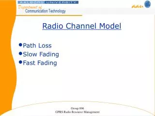
WINNER II Channel Models: Path Loss • WINNER II path loss models are developed based on results of measurements carried out within WINNER, as well as results from the open literature, and they are typically of the form • where d is the distance between the transmitter and the receiver in [m], fc is the system frequency in [GHz], the fitting parameter A includes the path-loss exponent, parameter B is the intercept, parameter C describes the path loss frequency dependence, and X is an optional, environment-specific term (e.g., wall attenuation in the A1 NLOS scenario) that are defined separately for each scenario • The models can be applied in the frequency range from 2 – 6 GHz and for different antenna heights • The free-space path loss is • The distribution of the shadow fading is log-normal, with a different standard deviation for each scenario Shahrnaz Azizi (Intel)
For each scenario in [2], either the variables of its corresponding path-loss model are provided or a full path loss formula is given. The table below provides data for scenario B1 (typical outdoor urban micro-cell) an Example of WINNER II Path Loss Model 4) d'BP is a function of the system frequency and the transmitter &receiver effective antenna heights,, see [2] 5) distances, d1 and d2 are defined with respect to a rectangular street grid, where the STA is on a street perpendicular to the street on which the AP is located (the LOS street), see Figure 4-3 in [2] Shahrnaz Azizi (Intel)
WINNER II – parameters for generic modelsComparison to IEEE .11n/ac • CDL: Clustered Delay Line - reduced variability CDL models with fixed large-scale and small-scale parameters are defined in [2] for calibration and comparison of different simulations. The parameters of the CDL models are based on expectation values of the generic models. Shahrnaz Azizi (Intel)
[1] IEEE 802.11-13/0657r1 “Usage models and requirements for IEEE 802.11 High Efficiency WLAN study group (HEW SG) – Liaison with WFA”, Laurent Cariou (Orange) [2] IST-WINNER II Deliverable 1.1.2 v.1.2. WINNER II Channel Models, IST-WINNER2. Tech. Rep., 2007 (http://www.ist-winner.corg/deliverables.html) [3] Report ITU-R M.2135-1 “ Guidelines for evaluation of radio interface technologies for IMT-Advanced”, 12/2009, (http://www.itu.int/dms_pub/itu-r/opb/rep/R-REP-M.2135-1-2009-PDF-E.pdf) References Shahrnaz Azizi (Intel)
Backup Shahrnaz Azizi (Intel)
IEEE Path Loss Model • The path loss model consists of a free space loss with a fixed slope of 2, up to a breakpoint distance and there after having a slope of 3.5. A different breakpoint distance was chosen for each model: Shahrnaz Azizi (Intel)