Download
1 / 54
540 likes | 754 Views
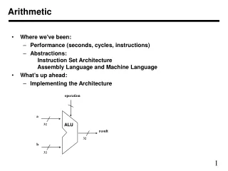
Chapter 7. CPU Arithmetic. CS.216 Computer Architecture and Organization. Overview. The Central Processing Unit (CPU) is the logical combination of the Arithmetic Logic Unit (ALU) and the system’s control unit In this section, we focus on the ALU and its operation Overview of the ALU itself

E N D
Chapter 7 CPU Arithmetic CS.216 Computer Architecture and Organization
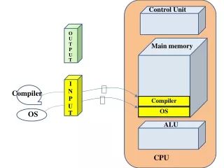
Overview • The Central Processing Unit (CPU) is the logical combination of the Arithmetic Logic Unit (ALU) and the system’s controlunit • In this section, we focus on the ALU and its operation • Overview of the ALU itself • Data representation (review!) • Computer Arithmetic and its H/W implementation • Reading: Text, Chapter 9
The ALU(1/4) • The ALU is that part of the computer that actually performs arithmetic and logical operations on data • All other elements of the computer system are there mainly to bring data to the ALU for processing or to take results from the ALU • Registers are used as sources and destinations for most ALU operations • In early machines, simplicity and reliability determined the overall structure of the CPU and its ALU • Result was that machines were built around a single register, known as the accumulator (Acc) • The accumulator was used in almost all ALU-related instructions
The ALU(2/4) Acc X ALU Acc = Acc op X
The ALU(3/4) • The power and flexibility of the CPU and the ALU is improved through increases in the complexity of the hardware • Use general register sets to store operands and , addresses, and results • Increase the capabilities of the ALU • Use special hardware to support transfer of execution between points in a program • Replicate functional units within the ALU to permit concurrent operations • Problem: design a minimal cost yet fully functional ALU • What building block components would be included?
The ALU(4/4) • Solution: • Only 2 basic components are required to produce a fully functional ALU • A bit-wide full adder unit • A 2-input NAND gate • As you recall from EE 2504, NAND is a functionally complete logic operation • Similarly, if you can add, all other arithmetic operations can be derived from addition. • To conduct operations on multiple bit words is clearly tedious! • Goal then is to develop arithmetic and logic circuitry that is algorithmically efficient while remaining cost effective
Integer Representation(1/6) • Sign-magnitude format • Positional representation using n bits • Left most bit position is the sign bit • 0 for positive number • 1 for negative number • Remaining n-1 bits represent the magnitude • Range: {-2n-1-1, +2n-1-1} • Examples (8-bit words): +42 = 00101010-42 = 10101010 • Problems: • Sign must be considered during arithmetic operations • Dual representation of zero (-0 and +0)
Integer Representation(2/6) • Ones complement format • Binary case of diminished radix complement (recall the 9s complement for base 10 numbers?) • Negative numbers are represented by a bit-by-bit complementation of the (positive) magnitude (the process of negation) • Sign bit interpreted as in sign-magnitude format • Examples (8-bit words): +42 = 00101010-42 = 11010101 • Still have a dual representation for zero (all zeros and all ones)
Integer Representation(3/6) • Twos complement format • Binary case of radix complement • Negative numbers, -X, are represented by the pseudo-positive number 2n - |X| • With 2n symbols • 2n-1-1 positive numbers • 2n-1 negative numbers • Examples (8-bit words): +42 = 00101010-42 = 11010110
Integer Representation(5/6) • Given the representation for +X, the representation for -X is found by taking the 1s complement of +X and adding 1 • +42 = 00101010 11010101 + 1 • -42 = 11010110 • Caution: avoid confusion with “2s complement format (representation) and the 2s complement operation
Integer Representation(6/6) • Converting between two word lengths (e.g., convert an 8-bit format into a 16-bit format) requires a sign extension: • The sign bit is extended from its current location up to the new location • All bits in the extension take on the value of the old sign bit • +18= 00010010+18= 00000000 00010010 -18= 11101110-18= 11111111 11101110
Integer Addition of n-bit numbers(2/5) • Use of a single full adder is the simplest hardware • Must implement an n-repetition for-loop for an n-bit addition • This is lots of overhead for a typical addition • Use a ripple adder unit instead • n full adder units cascaded together • In adding X and Y together unit i adds Xi and Yi to produce SUMi and CARRYi • Carry out of each stage is the carry in to the next stage
Integer Addition of n-bit numbers(3/5) • Worst case add time is n times the delay of each unit -- despite the parallel operation of each adder unit -- Order (n) delay • With signed numbers, watch out for overflow: when adding 2 positive or 2 negative numbers, overflow has occurred if the result has the opposite sign • Alternatives to the ripple adder • Must allow for the worst case delay in a ripple adder • In most cases, carry signals do not propagate through the entire adder
Integer Addition of n-bit numbers(4/5) • Provide additional hardware to detect where carries will occur or when the carry propagation is completed • Carry Completion Sensing Adders use additional circuitry to detect the time when all carries are completed • Signal control unit that add is finished • Essentially an asynchronous device • Typical add times are O(log n)
Integer Addition of n-bit numbers(5/5) • Carry Lookahead Adders • Predict in advance what adder stage of a ripple adder will generate a carry out • Use prediction to avoid the carry propagation delays -- generate all of the carries at once • Add time is a constant, regardless of the width, n, of the word -- O(1) • Problem: prediction in stage i requires information from all previous stages -- gates to implement this require large numbers of inputs, making this adder impractical for even moderate values of n
Integer Subtraction(1/2) • To perform X-Y, realize thatX-Y = X+(-Y) • Therefore, the following hardware is “typical”
Integer Multiplication(1/14) • A number of methods exist to perform integer multiplication • Repeated addition: add the multiplicand to itself “multiplier” times • Shift and add -- traditional “pen and paper” way of multiplying (extended to binary format) • High speed (special purpose) hardware multipliers • Repeated addition • Least sophisticated method • Just use adder over and over again • If the multiplier is n bits, can have as many as 2n iterations of addition -- O(2n) !!!! • Not used in an ALU
Integer Multiplication(2/14) • Shift and add • Computer’s version of the pen and paper approach:1011 (11)x 1101 (13)=========== 1011 00000 Partial products 101100 1011000=========== 10001111 (143)
Integer Multiplication(3/14) • The computer version accumulates the partial products into a running (partial) sum as the algorithm progresses • Each partial product generation results in an add and shift operation
Integer Multiplication(6/14) • To multiply signed numbers (2s complement) • Normal shift and add does not work (problem in the basic algorithm of no sign extension to 2n bits) • Convert all numbers to their positive magnitudes, multiple, then figure out the correct sign • Use a method that works for both positive and negative numbers • Booth’s algorithm is popular (recoding the multiplier)
Integer Multiplication(7/14) • Booth’s algorithm • As in S&A, strings of 0s in the multiplier only require shifting (no addition steps) • “Recode” strings of 1s to permit similar shifting • String of 1s from 2u down to 2v is treated as 2u+1 - 2v • In other words, • At the right end of a string of 1s in the multiplier, perform a subtraction • At the left end of the string perform an addition • For all of the 1s in between, just do shifts
Integer Multiplication(8/14) • Hardware modifications required in Figure 8.7 • Ability to perform subtraction • Ability to perform arithmetic shifting rather than logical shifting (for sign extension) • A flip flop for bit Q -1 • To determine operation (add and shift, subtract and shift, shift) examine the bits Q0Q-1 • 00 or 11: just shift • 10 : subtract and shift • 01 : add and shift
Integer Multiplication(9/14) Add/ Subtract A. Shift Q-1
Advantages of Booth: • Treats positive and negative numbers uniformly • Strings of 1s and 0s can be skipped over with shift operations for faster execution time
Integer Multiplication(12/14) • High performance multipliers • Reduce the computation time by employing more hardware than would normally be found in a S&A-type multiplier unit • Not generally found in general-purpose processors due to expense • Examples • Combinational hardware multipliers • Pipelined Wallace Tree adders from Carry- Save Adder units
Integer Division(1/7) • Once you have committed to implementing multiplication, implementing division is a relatively easy next step that utilizes much of the same hardware • Want to find quotient, Q, and remainder, R, such that D = Q x V + R
Integer Division(3/7) • Restoring division for unsigned integers • Algorithm adapted from the traditional “pen and paper” approach • Algorithm is of time complexity O(n) for n-bit dividend • Uses essentially the same ALU hardware as the Booth multiplication algorithm • Adder / subtractor unit • Double wide shift register AQ that can be shifted to the left • Register for the divisor • Control logic
Integer Division(5/7) • For two’s complement numbers, must deal with the sign extension “problem” • Algorithm: • Load M with divisor, AQ with dividend (using sign bit extension) • Shift AQ left 1 position • If M and A have same sign, A<--A-M, otherwise A<--A+M • Q0<--1 if sign bit of A has not changed or (A=0 AND Q=0), otherwise Q0=0 and restore *A
Integer Division(6/7) • Repeat shift and +/- operations for all bits in Q • Remainder is in A, quotient in Q • If the signs of the divisor and the dividend were the same, quotient is correct, otherwise, Q is the 2’s complement of the quotient
Floating Point Representation(1/12) • Integer fixed point schemes do not have the ability to represent very large or very small numbers • Need the ability to dynamically move the decimal point to a convenient location • Format: +/-M x R +/-E • Mantissas are stored in a normalized format • Either 1.xxxxx or 0.1xxxxx • Since the 1 is required, don’t need to explicitly store it in the data word -- insert it for calculations only
Floating Point Representation(2/12) • Exponents can be positive or negative values • Use biasing (Excess coding) to avoid operating on negative exponents • Bias is added to all exponents to store as positive numbers • For a fixed n-bit representation length, 2n combinations of symbols • If floating point increases the range of numbers in the format (compared to integer representation) then the “spacing” between the numbers must increase • This causes a decrease in the format’s precision
Sign Bit Exponent Significand/Fraction Floating Point Representation(3/12) • If more bits are allocated to the exponent, range is increased at the expense of decreased precision • Similarly, more mantissa bits increases the precision and reduces the range • The radix is chosen at design time and is not explicitly represented in the format • Small -- smaller range • Large -- increased range but loss of significant bits as a result of mantissa alignment when normalizing
Floating Point Representation(4/12) • Problems to deal with in the format • Representation of zero • Over and underflow and how to detect • Rounding operations • IEEE 754 format • Defines single and double precision formats (32 and 64 bits) • Standardizes formats across many different platforms • Radix 2 • Normalized Format 1.xxxxxxx
Floating Point Representation(5/12) • Single • Range 10-38 to 10+38 • 8-bit exponent with 127 bias • 23-bit fraction • Double • Range 10-308 to 10+308 • 11-bit exponent with 1023 bias • 52-bit fraction
Floating Point Representation(9/12) • Floating point arithmetic operations • Addition and subtraction • Align mantissas • Add or subtract mantissas • Post normalize • Multiplication • Add exponents • Multiply mantissas • Post normalize • Division • Subtract exponents • Divide mantissas • Post normalize