Download
1 / 38
380 likes | 565 Views
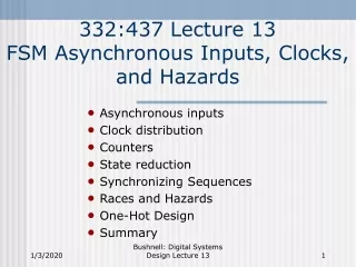
Handling Asynchronous Inputs. Asynchronous Signals. Definition: A signal that can change at any time with respect to the clock. Examples: Push buttons Keystrokes Digital signals from different clock domain. Two Problems with Asynchronous Inputs. Flip flops could become metastable

E N D
Handling Asynchronous Inputs ECEn 224
Asynchronous Signals • Definition: A signal that can change at any time with respect to the clock. • Examples: • Push buttons • Keystrokes • Digital signals from different clock domain ECEn 224
Two Problems with Asynchronous Inputs • Flip flops could become metastable • State machines may transition to incorrect next state These are two independent problems. ECEn 224
Problem #1 Metastability ECEn 224
Asynchronous Signals • Problem: Asynchronous signals do not always respect setup and hold times • Asynchronous signals may change at any time ok ok bad bad ok ok tsetup thold Clock ECEn 224
R=0 Q=1 Q’=0 S=0 Metastability • Imagine if R is pulsed high for a very short time then goes back low… • Could it impart just enough energy to get Q halfway between ‘1’ and ‘0’? • Latch might hang at the midway point for some time • Could be a short time, could be a long time • This is called metastability ECEn 224
Metastability • Violating tsetup for a D flip flop can cause very short pulses on signals Y and Z, and make flip flop metastable D Y Q Q’ Z CLK ECEn 224
Metastability • Once a flip flop goes metastable, it is impossible to bound how long it will remain there Analogy: Roll ball up roof just hard enough to get it to balance on top… ECEn 224
Metastability • Once a flip flop goes metastable, it is impossible to bound how long it will remain there Analogy: Roll ball up roof just hard enough to get it to balance on top… When will it come down? ECEn 224
Probability of Metastability • The probability of an asynchronous signal causing metastability in a given clock cycle is very low • However, there are millions or even billions of clock cycles every second • Mean Time Between Failure (MTBF) quantifies how often a flip flop with an asynchronous input is likely to go metastable • MTBF depends on: • Flip flop’s clock frequency • Frequency of changes on the asynchronous input • Electrical characteristics of the flop flop • Typical MTBF numbers can range from minutes for high frequency systems to thousands of years for slower devices ECEn 224
D Q D Q Metastability Solutions • Solution #1: Specially-designed flip flops that are particularly resistant (hardened) • Solution #2: Multiple FF’s in series increases resistance to metastability • At the expense of response time AsynchronousIn SynchronizedOut Could also be hardened flip flops ECEn 224
Problem #2 May Lead to Wrong Next State (No metastability involved here…) ECEn 224
Wrong Next State • Asynchronous inputs might cause the wrong next state to be loaded • Two possible causes: • Unequal logic path lengths (Cause A) • False outputs on IFL outputs (Cause B) ECEn 224
D Q D Q A’ 10ns 5ns 00 A 11 Cause A: Unequal Path Lengths IFL N1 C1 A clk N0 C0 clk ECEn 224
D Q D Q A’ 10ns 5ns 00 A 11 Cause A: Unequal Path Lengths IFL N1=0 Q1=0 clk A=0 N0=0 Q0=0 clk Time t = 12 ns ECEn 224
D Q D Q A’ 10ns 5ns 00 A 11 Cause A: Unequal Path Lengths IFL N1=0 Q1=0 clk A1 N0=0 Q0=0 clk Time t = 13 ns ECEn 224
D Q D Q A’ 10ns 5ns 00 A 11 Cause A: Unequal Path Lengths IFL N11 Q1=0 clk A1 N0=0 Q0=0 clk Time t = 18 ns ECEn 224
D Q D Q A’ 10ns 5ns 00 A 11 Cause A: Unequal Path Lengths IFL N11 Q11 clk A1 N0=0 Q0=0 clk Time t = 20 ns (clock rises) ECEn 224
A’ 00 A 11 Erroneous State Transition CLK A N1 N0 CurrentState 00 10 0 5 10 25 30 5ns Wrong next state!! 10ns ECEn 224
A’ 00 A 11 Erroneous State Transition CLK Danger period A N1 N0 CurrentState 00 10 0 5 10 25 30 5ns 10ns ECEn 224
D Q D Q D Q 10ns 5ns Solution #1: Synchronize Signal A IFL IFL now sees synchronous input N1 C1 clk A N0 C0 clk clk Synchronizing flip flop is still susceptible tometastability due to setup time violations. But that is a different problem with previously-seen solutions. ECEn 224
D Q D Q A’ A’ 10ns 5ns 01 00 A A 11 11 Solution #2: Use Gray Codes for States Will never have casewhen both pathstransitioning… IFL N1 C1 A clk N0 C0 clk State change will occur or it won’t… ECEn 224
Cause B: False Outputs • Gray coding state transitions doesn’t always work! • We can still have false outputs on our input forming logic • These hazards can also lead to incorrect transitions ECEn 224
A’ B F A C Logic Hazards Asynchronous input A F = A’B + AC This is the conventional K-map solution ECEn 224
Gates Have Real Timing… A g1 g1 A’ B=1 F g2 A g2 C=1 F Called a false output ECEn 224
Gates Have Real Timing… A g1 g1 A’ B=1 F g2 A g2 C=1 F If the clock edge occurs here… you’re toast! ECEn 224
Hazard-Free Logic Design • Make sure all adjacent 1’s are covered by the same prime implicant • Add redundant prime implicants as needed A’ g1 B g2 F A C Redundant butwill eliminatefalse output B g3 C On ABC = ‘111’ to ABC = ‘011’, g3 will hold F high entire time. ECEn 224
A’ g1 B=1 g2 F A C=1 B=1 g3 C=1 No False Output… A g1 g2 g3 F ECEn 224
IFL S’ D Q D Q N1 C1 10ns 5ns 01 A clk S N0 C0 11 clk Solution #3 • Use both gray code states and hazard-free logic minimization • Gray code encoding ensure only one state bit changes • Solves the unequal path problem • HFLM ensures no hazards (false outputs) exist on input forming logic ECEn 224
Asynchronous Input Problem Summary • Problem #1: Asynchronous inputs can cause flip flops to enter a metastable state • Problem #2: Asynchronous inputs can cause invalid state transitions A) Different propagation delays on IFL paths to different state bits B) False outputs on IFL outputs ECEn 224
Solutions Summary • Metastability • Solution #1: Use hardened flip flops • May not be available • Solution #2: Add flip flops in series to decrease susceptibility • Latency may cause problems, if we need to react immediately • Invalid State Transitions • Solution #1: Synchronize asynchronous inputs with a flip flop • Simplest solution • Latency may cause problems, if we need to react immediately • Solution #2: gray code state encoding (doesn’t always work) • Solution #3: gray code + hazard-free IFL • Takes extra hardware • May require additional states to get gray code transitions • Use when need to react quickly to input • FF’s still susceptible to metastability • HFLM only works for single-input changes The same solution! ECEn 224
Other Asynchronous Input Issues ECEn 224
Multiple Asynchronous Inputs • What if we have a state transition that depends on multiple asynchronous inputs? A’•B’ S0 A’•B A S2 S1 ECEn 224
Multiple Asynchronous Inputs • Break up the states so that only one transition is dependant on each input A’•B’ S0 B’ S0 A’ A A’•B S2 A S1 B S2 S1 S3 ECEn 224
Multiple Clock Systems • When you make up the rules • You can cheat… • In this class we cheat: • One global clock simplifies our work • In the real world: • Systems have multiple clocks ECEn 224
Multi-clock System • This is a PCI Express board that plugs into a computer’s motherboard RAM (DDR SDRAM) FPGA Video DAC PCI-E Interface (PHY) PCI-E Connector ECEn 224
Multi-clock System • This is a PCI Express board that plugs into a computer’s motherboard 200 MHz How do they talk to each other? 100 MHz 25.175 MHz 250 MHz 2.5 GHz ECEn 224
Multi-Clock Systems • This system has multiple clock domains • Signals that cross domains look like asynchronous signals to the other domain • For simple control signals, we can use one of the methods discussed in this lecture • Synchronizing flip flops • Hazard free logic + gray codes • When data transfer is involved, the required solutions are more complicated (ECEn 320) ECEn 224