Download
1 / 37
370 likes | 461 Views
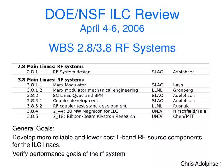
DOE/NSF ILC Review April 4-6, 2006 WBS 2.8/3.8 RF Systems. General Goals: Develop more reliable and lower cost L-band RF source components for the ILC linacs. Verify performance goals of the rf system. Chris Adolphsen. ILC Linac RF Unit (1 of ~ 600). Gradient = 31.5 MV/m

E N D
DOE/NSF ILC ReviewApril 4-6, 2006WBS 2.8/3.8 RF Systems General Goals: Develop more reliable and lower cost L-band RF source components for the ILC linacs. Verify performance goals of the rf system Chris Adolphsen
ILC Linac RF Unit (1 of ~ 600) Gradient = 31.5 MV/m Bunch Charge = 2e10 e Rep Rate = 5 Hz # of Bunches = 2967 Bunch Spacing = 337 ns Beam Current = 9.5 mA Input Power = 311 kW Fill Time = 565 ms Train Length = 1000 ms (8 Cavities per Cryomodule)
3.8.1 Marx Modulator • Definition of Work Package • Marx is ACD Alternate Design to BCD Bouncer Modulator • Motivation: Reduce cost, size and weight, Improve efficiency, eliminate oil from tunnel • FY06 Program • Demonstrate basic operation with full power prototype by end FY06. • Begin design of DFM Unit for service in klystron test stands at SLAC and where needed. • Down-select to ACD when successful.
ILC Baseline Pulse Transformer Modulator IGBT’s
Marx Generator Modulator 12 kV Marx Cell (1 of 16) • IGBT switched • No magnetic core • Air cooled (no oil)
Full Modulator(~ 2 m cubed) 150 kW Air-CoolLoad for Testing
Marx Features • Direct-coupled voltage stack of ten 12-kV cells producing 140A pk @ 1.5 msec. • Cell can operate with failed components. • 4/5 redundant solid state output, re-charging switch banks. • Modulator functions with up to 2 failed drivers • 10 needed, 12 available • Vernier cells correct flat top to +/-0.5%. • Second stage correction also being studied to approach +/-0.1% if possible. • Buck regulators (2) have 4/5 switch redundancy
Development Team • Engineering • G. Leyh, Lead; Piotr Blum, C. Burkhart, J. Olsen, SLAC • C. Brooksby, E. Cook, Bechtel/LLNL • Consultants • S. Cohen, LANL • J. Frisch, K. Jobe, SLAC • G. Majumdar, Mitsubishi • H. Pfeffer, FNAL • Industrial Participants • Diversified Technologies, Bedford MA • ISA, Dublin CA • Stangenes Industries, Palo Alto CA
Marx Modulator Status • Modulator support structure, backbone, complete • First prototype Marx Cell ready for testing. • Equipotential rings, connection planes complete • PPS system for modulator 30% complete • Air cooled 150 kW test load25% complete • 12kV single-cell test stand ready for operation • As of March 1, 2006, • Labor charges = 187 k$ (576 k$ allocated) • M&S charges = 280 k$ (370 k$ allocated)
3.8.2 SC Linac Quad and BPM • Goals: • Characterize field properties of a prototype linac SC quad. • Verify quad center moves < 5 microns when the field strength is changed by 20% as required for beam based alignment. • Develop cavity BPMs with micron-scale resolution for multi-bunch (200 ns spacing) operation. • Project Description: • Acquired a prototype SC linac quad (80 mm bore, cos[2f] type) from CIEMAT/DESY. Building a warm-bore cryostat for it at SLAC. • Characterize quad magnetic field with a rotating coil, in particular, to measure any motion of the magnetic center when the field strength is varied. • S-band rf cavity bpms have been designed and a triplet built that will be tested with beam in End Station A (ESA). • BPMs have half the nominal aperture to simplify testing design concept and because it would be advantageous for the ILC. • In FY07, propose to test quad and bpms with beam to demonstrate required quad shunting performance.
Field Map ILC Linac SC Quad/BPM Evaluation S-Band BPM Design (36 mm ID, 126 mm OD) Cos(2F) SC Quad (~ 0.7 m long) He Vessel SC Coils Iron Yoke Block Al Cylinder
For Magnetic Center Measurements, Adapt Apparatus Developed for NLC NC Quads Series of measurements (8 minutes each) of a 25 cm long NLC prototype quad - shows that sub-micron resolution is possible and systematics are controllable. Currently designing longer, wider coil for SC Quad test – will qualify it first with a NC Quad. X Center (microns) Measurement
S-Band (2.86 GHz) BPMMode Spectrum (monopole mode signals suppressed geometrically)
SC Quad/BPM Status • Magnet received from DESY in January after initial testing there in a vertical Dewar. Gas-filled leads received in March. • With help of Tom Nicol at FNAL, developed a low heat loss, stable support design for the He vessel. May adopt similar support structure for the ILC linac. • Cryostat drawings currently being submitted to the SLAC shops. • First tests of new magnet measuring coil planned during the next month using a NC quad. SC quad measurements planned for July. • BPM triplet built and installed on girder in ESA. Beam test to start April 24. • As of March 1, 2006 • Labor charges – 112 k$ (144 k$ allocated, 240 k$ requested last October) • M&S charges – 126 k$ (205 k$ allocated, 250 k$ requested last October) • Project at ~ 50% point with about half of the requested funding spent.
3.8.3 Coupler Development(LLNL / SLAC) • Goals: • Understand rf processing limitations (typically takes > 100 hours per coupler). • Assess effect of coupler coatings, bellows, and widows on processing time. • Propose changes to TTF3 design to improve performance and lower cost. • Project Description: • Eleven coaxial sections (40 mm ID, 70 Ohm) will be prepared that vary in terms of material (SS or Cu), bellows (none, 5 or 10 folds) and windows (with and without). • A general purpose waveguide (WR650) to coax adaptor has been designed to power the test sections in vacuum. • Use the L-band rf source that has been configured at NLCTA (currently produces 3.3 MW, 1 msec pulses at 5 Hz: need only ~ 2 MW).
Coupler Processing Studies Concern that the surface field variations in the bellows and near the windows may lead to excessive mulitpacting. Coupler Surface Field To understand processing limitations, plan to process coupler components individually. In particular, determine if bellows or the windows are the source of the long processing time.
Coupler Development Status • Have decided on basic layout of system to test coupler parts – drawings are being prepared • Setup uses a detachable center conductor and 50 cm long test sections • As of March 1, 2006 • 15 k$ labor charges (180 k$ allocated) • Zero M&S (100 k$ allocated) • Ready for first tests this Summer.
2.8.1 RF System Design • Doing tracking simulations of multipacting in the TTF3 couplers in conjunction with coupler R&D program. Will produce 3D map of multipacting 'activity' -vs- rf power and longitudinal position along the coupler outer surface. • Studying ways to reduce rf distribution costs: considering three changes to the basic design: • The circulators in the TDR design are a big cost item (~ 35% of total distribution system). To eliminate them, power the cavities in pairs using 3 dB hybrids, which would still isolate them. • Develop a variable tap-off system to feed the cavity pairs. • Replace the three-stub tuner with a mechanical squeeze type phase shifter that would adjusted after the system is setup. • As of March 1, 2006 • 83 k$ of labor charges (126 k$ allocated)
Bellows Primaries -Green, Secondaries- Red Multipacting Simulation of TTF3 Coupler “Cold Side”
Baseline RF Distribution System Similar to TDR and XFEL scheme. Alternate RF Distribution System With two-level power division and proper phase lengths, reflections from pairs of cavities are directed to loads. Also, fewer types of hybrid couplers are needed in this scheme. There is a small increased risk to klystrons (total reflection from a pair of cavities sends < 0.7% of klystron power back to the klystron.)
FY07-09 RF System Program • Goal: demonstrate viable, cost-optimal rf source for ILC. Operate six ‘production’ sources from industrial vendors by FY10. Supply power source and couplers for RF unit test at FNAL. • SLAC has substantial expertise in this area and ILC Americas expects SLAC to lead this program. Would be responsible for all components from the AC power to the couplers. • Program would be comparable in size to that during NLC rf development. • Schedule meshes well with FNAL cryomodule program. • Schedule allows for testing to establish > 2000 hour MTBF’s, which is minimum allowable in particular availability models.
WBS 3.8.4 Yale University Beam Physics LaboratoryPROGRESS REPORT20-MW MAGNICON FOR ILCsupported under DoE grant DE-FG02-05 ER 41394, 9/1/05 – 8/31/08 Program objectives: (a) To provide laboratory infrastructure at Yale needed to allow tests of a 20-MW, 1.3 GHz magnicon amplifier being designed and built to be an alternative RF source for ILC. (b) To coordinate closely with Omega-P, Inc. in its design and fabrication of the 20-MW magnicon, anticipating future tests at Yale. Funding profile:
Progress to date (9/1/05 - 3/21/06) A. At Yale Beam Physics Lab, room 112 (M.A.LaPointe, J.L.Hirshfield): 1. added 72 kW ac power, to bring total up to 150 kW; 2. relocated water pipes so that shielding door can close ($11k from Yale towards cost); 3. ordered 150 kW heat exchanger. B. At Omega-P (V.P.Yakovlev, J.L.Hirshfield): 1. refined conceptual design for magnicon; 2. made preliminary simulations for TE111-mode output cavity (reduced RF surface field in output cavity, compared with TM110-mode and with MBK); 3. began negotiations with potential industrial partner for fabrication of tube and contribution of 30 MW / 80 kW modulator, suitable for 1.6 ms pulse width, ~1 Hz rep rate operation of 20-MW, 1.3 GHz magnicon.
20-MW, 1.3-GHz MAGNICON AMPLIFIER FOR ILCPreliminary design layout and design specifications
WBS 3.8.5 Ribbon-Beam Klystron Research: Improving Efficiency in High-Power Klystrons Chiping Chen Plasma Science and Fusion Center Massachusetts Institute of Technology DOE ILC Review April 5, 2006 33 DOE ILC Review Chiping Chen, Intense Beam Theoretical Research Group
Ribbon-Beam Klystron • Klystron is a high capital cost, high operating cost item for ILC. • Ribbon-beam klystron (RBK) is a leading ACD choice, because it is better than the multi-beam klystron (MBK) BCD choice. • Higher efficiency (75% vs. 65%) • Single beam vs. 6 beams • Energy-free permanent magnet vs. energy-consuming pulsed magnet • RBK provides potentially the following savings: • Klystron hardware: 66% (or $60M) saving. • RF system electricity: 20% (or $20M/year) saving. 34 DOE ILC Review Chiping Chen, Intense Beam Theoretical Research Group
RBK (Ribbon-Beam Klystron) MBK (Multi-Beam Klystron) SLAC XP3 Klystron h = 0.8 - 0.2 mP Ribbon Beam Improves Klystron Efficiency 35 DOE ILC Review Chiping Chen, Intense Beam Theoretical Research Group
Current Status and Budget • 2005 Status • Carried out innovative research to successfully reduce the twist angle of the elliptic beam (2005). • Applied results of ribbon beam physics studies in our consideration of design options for the ribbon-beam transport system (2005). • Determined the feasibility of magnet engineering required for focusing the elliptic electron beam (2005). • Developed a small-signal theory of RBK (2005). • 2005-2006 Budget • Total Amount Funded: $30K • $5K left 36 DOE ILC Review Chiping Chen, Intense Beam Theoretical Research Group
Summary • Have made good progress toward achieving FY06 goals. • Gaining expertise in low-frequency, long-pulse rf sources required for ILC, and beam related issues with SC quads and ‘cold’ BPMs. • Starting in FY07, will expand work toward producing a robust klystron and a lower cost rf distribution system. • In a good position to ramp up program in the next few years to produce several prototype ILC rf sources.