Download
1 / 14
260 likes | 1.08k Views
CFD Pre-Lab 1 Simulation of Laminar Pipe Flow Seong Mo Yean, and Timur Dogan 10/14/2013. Outline. Overview of Pipe Flow CFD Process ANSYS Workbench ANSYS Design Modeler (Geometry) ANSYS Mesh ANSYS Fluent Physics (Setup) Solution Results. Overview of Pipe Flow.

E N D
CFD Pre-Lab 1Simulation of Laminar Pipe FlowSeong Mo Yean, and Timur Dogan10/14/2013
Outline • Overview of Pipe Flow • CFD Process • ANSYS Workbench • ANSYS Design Modeler (Geometry) • ANSYS Mesh • ANSYS Fluent • Physics (Setup) • Solution • Results
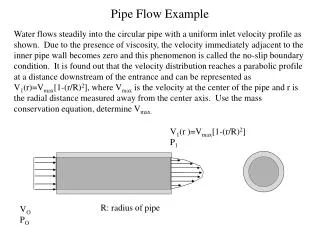
Overview of Pipe Flow • Simulation of laminar pipe flow will be conducted for this lab • Axial velocity profile, centerline velocity, centerline pressure, and wall shear stress will be analyzed • Computational fluid dynamics (CFD) results for friction factor and velocity profile will be compared to analytical fluid dynamics (AFD) • This lab will cover concept of laminar vs. turbulent flow and developing length for pipe flows Flow visualization between two parallel plates (starts at 14:25)
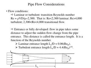
Overview of Pipe Flow • Flow in pipe with Reynolds(Re) number where U inflow velocity, D diameter of pipe, kinetic viscosity • Laminar : Re < 2300 • Turbulent : Re > 2300 • Differences between laminar and turbulent flow • (mean) Velocity profile • Pressure drop • Developing length • Wall shear stress and friction factor Note: Refer to Chapter 8 of your book for more details Flow visualization of transition from laminar to turbulent flow
Physics Geometry Results Mesh Solution Solution Methods (ANSYS Fluent - Solution) Pipe (ANSYS Design Modeler) General (ANSYS Fluent - Setup) Structure (ANSYS Mesh) Plots (ANSYS Fluent- Results) Model (ANSYS Fluent - Setup) Uniform (ANSYS Mesh) Graphics and Animations (ANSYS Fluent- Results) Boundary Conditions (ANSYS Fluent -Setup) Laminar Monitors (ANSYS Fluent - Solution) Reference Values (ANSYS Fluent - Setup) Solution Initialization (ANSYS Fluent -Solution) CFD Process • The overall procedure for simulation of pipe flow is shown on chart below • Although we will be making the mesh before we define the physics you have to know the physics to design appropriate mesh.
ANSYS Workbench (Overview) • Design your simulation using ANSYS Workbench ANSYS Mesh (Mesh) ANSYS Design Modeler (Geometry) ANSYS Fluent (Physics, Solution and Results)
ANSYS Design Modeler (Geometry) • Symmetric property of the flow is used to create 2D representation of the 3D pipe flow R D Wall L Flow Inlet Outlet Center
ANSYS Mesh • Create uniform grid distribution
ANSYS Fluent • Using ANSYS fluent define physics of the flow, solve CFD simulation and analyze results Physics (Setup) Results Solution
ANSYS Fluent Physics r Wall – No slip BC • Laminar flow • Air properties • Boundary Conditions (BC) • No-slip: velocities are zero (), pressure gradient () is zero • Symmetric: radial velocity is zero (), gradients of axial velocity and pressure are zero (, ) • Inlet velocity: uniform constant velocity () • Outlet: (gauge) pressure is imposed to the boundary (, ) Flow Inlet – Velocity inlet BC Outlet – Pressure outlet BC x Center – Axisymmetric BC Zero slop at center or
ANSYS Fluent Solution • A limiting behavior in the solution of the equations • Represented by the history of residuals or errors made by previous iterative solutions. • A converged solution is not necessarily an accurate one due to iteration number, domain size, mesh resolution and numerical schemes • Continuity, momentum equation have their own residual histories.
ANSYS Fluent Results • Developed length is distance from entrance to a point where flow is fully developed. • Fully developed flow does not change velocity profile or velocity gradient in axial direction is zero. • Pressure drops linearly. • Axial velocity or skin friction distribution along axis can be used to determine the length. Developed region Developing region
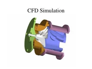
ANSYS Fluent Results • Flow can be visualized in detail using CFD
Questions? • Bring your Data Reduction Sheet for the CFD Labs • Deadline for CFD Lab report is two weeks after your CFD lab (not pre-lab) • Use lab drop-box when turning in your lab reports • Come to the office hours for help