Download
1 / 13
130 likes | 146 Views
Proteus 1000 Series flow switches are designed to monitor the flow of fluid through a line. They are frequently used to assure that water is flowing in a cooling circuit, however they may be used in a wide variety of applications with many different fluids. <br>http://proteusind.com/<br>

E N D
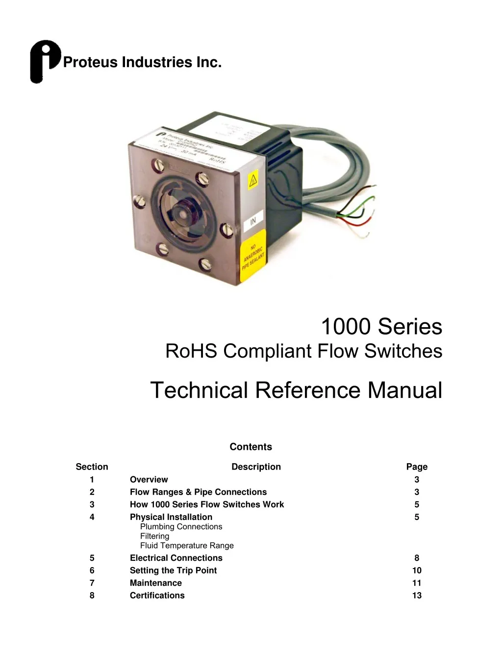
Proteus Industries Inc. 1000 Series RoHS Compliant Flow Switches Technical Reference Manual Contents Description Section 1 2 3 4 Page 3 3 5 5 Overview Flow Ranges & Pipe Connections How 1000 Series Flow Switches Work Physical Installation Plumbing Connections Filtering Fluid Temperature Range Electrical Connections Setting the Trip Point Maintenance Certifications 5 6 7 8 8 10 11 13
Section 1: Overview Proteus 1000 Series flow switches are designed to monitor the flow of fluid through a line. They are frequently used to assure that water is flowing in a cooling circuit, however they may be used in a wide variety of applications with many different fluids. Important Safety Information: NOTE and CAUTION statements are used throughout this manual to highlight important operational and safety information. ? NOTE statements provide details that are important to the successful understanding and application of the system. CAUTION statements identify conditions or practices that could result in damage to the equipment or other property. WARNING statements identify conditions or practices that could result in personal injury or loss of life. Technical Support For technical or application assistance, contact: Proteus Industries Inc. 340 Pioneer Way Mountain View, CA 94041 Phone: (650) 964-4163 Fax: (650) 965-0304 E-mail: tech@proteusind.com 5-Year Warranty The full text of the Proteus Industires warranty is available at www.proteusind.com/warranty/ 1000TRM-002 Page 2 of 13 May 2007
Section 2: Flow Ranges, Materials and Pipe Connections Table 1 lists the flow ranges, connections materials available for the 1000 Series flow switches. NOTE The lower limit of the flow range is the lowest flow at which the flow switch can be set to operate. The upper limit of the flow range is that flow rate at which the rotor is spinning at a rate of 40 rps, or that flow at which pressure drop across the flow sensor is 100 psi (670 kPa). Flow ranges listed are for water at 25°C. ? Flow Range Part Number Connection 316 Stainless Steel 01004SN03 01004SN1 01004SN2 01006SA2 01004SN4 01006SA4 01006SN9 01008SA10 01008SN14 01012SN16 01012SA16 01012SN40 01016SN40 01016SA40 01016SN60 GPM LPM Polypropylene Brass 0.05 – 0.3 0.06 – 0.6 0.1 – 1.0 0.2 – 2.5 0.2 – 2.5 0.3 – 4.5 0.3 – 4.5 0.6 – 9.0 0.6 – 10.0 0.8 – 10 1.0 – 14 1.2 – 16 1.2 – 16 1.5 – 19 3 – 40 4 – 40 4 – 40 4 – 50 5 – 60 0.2 – 1.5 0.3 – 2.3 0.4 – 3.8 0.75 – 9.5 0.75 – 9.5 1.1 – 17 1.1 – 17 2.3 – 34 2.3 – 38 3 – 38 3.8 – 53 4.5 – 60 4.5 – 60 6 – 72 11 – 150 15 – 150 15 – 150 15 – 190 18 – 225 ¼" FNPT ¼" FNPT ¼" FNPT ¼" FNPT 01004BN03 01004BN1 01004BN2 01004BN4 01006BN9 01008BN14 01012BN16 01012BN40 01016BN40 01016BN60 01004PN06 01004PN1 01004PN2 01004PN4 01006PN10 01008PN14 01012PN19 01016PN50 9⁄16-18 SAE ¼" FNPT 9⁄16-18 SAE ⅜" FNPT ⅜" FNPT ¾-16 SAE ½" FNPT ¾" FNPT 11⁄16-12 SAE ¾" FNPT ¾" FNPT 1" FNPT 15⁄16-12 SAE 1" FNPT 1" FNPT Table 1: Flow Ranges and Pipe Connections Other Wetted Materials Available Materials Component Standard Optional Rotor O-Ring Rotor Shaft ® Viton & Kynar are registered marks of DuPont PPS Viton® 316 Stainless Steel Kynar® Buna-N, Silicone rubber, etc Alumina, Sapphire 1000TRM-002 Page 3 of 13 May 2007
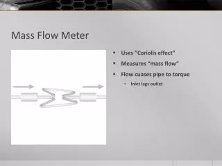
Section 3: How 1000 Series Flow Switches Work The rotor spins when liquid flows through the flow meter. Mangets in the rotor switch a Hall Effect sensor mounted in the meter body. The resulting pulse train is converted by the electronics to a voltage that is proportional to the linear velocity at which the liquid flows through the meter. Switching Hall Effect sensor Rotor Magnet The measured output voltage is continuously compared to a user-selected trip point voltage. When the measured voltage is above the trip point voltage, the built-in relay remains in its active state. If the measured voltage falls below the trip point because of reduced or stopped flow, the relay changes to its inactive state, signaling an alarm condition to your control system. NOTE ? If you select the Normally Open (NO) connections, the contacts will open when the relay is switched to its inactive state. If you select the Normally Closed (NC) connections the contacts will close when the relay is switched to its inactive state. Section 4:Physical Installation CAUTION! Avoid mounting any plumbing connections directly above electronic controls or instruments that can be damaged by leaking liquid. If a 1000 Seies flow switch is mounted in a vertical pipeline, any leakage from the topmost connection could enter the electronics unit and cause permanent damage to the electronics. Dimensions Outline and 3D drawings of 1000 Series flow switches can be viewed on the Proteus Industries website at http://www.proteusind.com/1000/1000drawings.html Pipe or tubing mounting If rigid piping or tubing is used, the flow switch may be supported by direct connection to the pipe or tubing. 1000TRM-002 Page 4 of 13 May 2007
Panel mounting To mount the sensor behind a panel, two (2) of the faceplate securing screws will need to be replaced with longer screws to compensate for the thickness of the panel. Ensure that the screws are not so long as to touch the bottom of the tapped hole, or rip through the back of the plastic body if over-tightened. Evenly space up to six (6) holes for 8-32 screws on a 2.5” circle. Using the two (2) holes on the horizontal plane is usually sufficient to support smaller flow sensors and all plastic sensors. If you wish the rotor to be visible, cut a 1¾” diameter hole with the same center. Figure 1: Panel Mounting of 1000 Series Flow Switch 1. Remove the screws holding the faceplate to the sensor body. 2. Place the sensor behind the panel and insert the longer screws you have selected. 3. Secure the screws in the body with a torque of ~ 10 in-lb. (Finger tight with a flathead screwdriver.). Plumbing Connections CAUTION! Before connecting a flow switch into your fluid line, verify that the normal flow rates expected in that line are within the operating range of the sensor as shown in Table 1 Extended use above the rated maximum flow rate of the sensor will reduce its useable life. ?It is recommended that connections to brass or stainless steel flow sensor be made with similar materials to minimize potential corrosion damage NOTE 1000TRM-002 Page 5 of 13 May 2007
NOTE ? The flow response of the sensor, and thus its output response, may be dependent on the internal diameter (ID) of an incoming pipe or the ID of a tube connection. If the ID of your pipe or tube fitting where it connects to the inlet port is LESS than the value shown in Table 2, pre-calibrated trip points may be invalid. Part Number Minimum ID of Pipe or Connection Connection Polypropylene 01004PN06 01004PN1 01004PN2 01004PN4 01006PN10 01008PN14 01012PN19 01016PN50 Brass 01004BN03 01004BN1 01004BN2 01004BN4 01006BN9 01008BN14 01012BN16 01012BN40 01016BN40 01016BN60 316 Stainless Steel 01004SN03 01004SN1 01004SN2 01006SA2 01004SN4 01006SA4 01006SN9 01008SA10 01008SN14 01012SN16 01012SA16 01012SN40 01016SN40 01016SA40 01016SN60 ¼" FNPT ¼" FNPT ¼" FNPT ¼" FNPT 9⁄16-18 SAE ¼" FNPT 9⁄16-18 SAE ⅜" FNPT ⅜" FNPT ¾-16 SAE ½" FNPT ¾" FNPT 11⁄16-12 SAE ¾" FNPT ¾" FNPT 1" FNPT 15⁄16-12 SAE 1" FNPT 1" FNPT Not Sensitive Not Sensitive 0.118” 0.188” 0.188” 0.25” 0.25” 0.375” 0.400” 0.400” 0.460” 0.610” 0.610” 0.610” 0.800” 0.800” 0.800” 1.000” 1.000” Table 2: Minimum ID of Pipe or Connection NOTE The flow response of a 1000 Series flow switch may be dependent on the form of any device attached to the inlet connection and other closely located up-stream devices. Elbows, T-pieces, valves and filters located immediately up-stream from the flow sensor can introduce a swirling motion to the liquid flow. This swirling motion reduces the linear velocity of the flow stream. We recommend that a straight run of pipe of 10 x pipe ID be placed between the flow switch and any up-stream devices to minimize these effects. Appropriate calibration procedures must be used to provide accurate trip point settings in systems in which elbows or T-pieces must be attached to the inlet connection. 1000 Series flow switches are typically unaffected by the form or proximity of devices downstream. ? 1000TRM-002 Page 6 of 13 May 2007
Sensor Orientation For the best results, 1000 Series flow switches should be mounted with the faceplate in the vertical plane. Mounting the device with the flow connections uppermost can help eliminate entrained air from your system. Connecting NPT Pipe Thread Connections Pipe threads seal by making metal-to-metal or plastic-to-plastic contact between male and female components. Consequently, they are particularly prone to the damaging effects of galling, which occurs when two surfaces move against each other under pressure. When installing pipe threads, it is essential to use a high-quality lubricating and sealing material. CAUTION! Do NOT use anaerobic pipe sealants such as LOCTITE or SWAK brand sealants with these sensors. Solvents used in these materials will cause cracking of polysulfone faceplates. • Use Teflon tape or a PTFE-based liquid sealant to provide lubrication for the junction and a leak-tight connection at both the input and output connections. Real-Tuff and Hercules are two of many suitable brands of PTFE-based sealants. Do not over-tighten the connection. Refer to instructions for installation of the mating fittings for information on torque requirements. Leak testing of all connections in your flow circuit is recommended. Pressurizing the system with air and external testing with a diluted soap solution can help identify leaking connections. • • SAE Straight Thread Connections With these connectors, an o-ring makes the seal while the threads hold the connecting assembly in place. Straight thread connections should receive a small amount of high-pressure lubricant before installation to prevent galling. Non-Adjustable Fittings 1. Bring the non-adjustable fitting into firm contact with the face of the port, using a wrench. 2. Check to be certain that the o-ring fits easily into the non-threaded receiving area of the port and that is not pinched. 1000TRM-002 Page 7 of 13 May 2007
Adjustable Fittings 1. Ensure that the locknut is positioned so the back-up washer is in contact with the beginning of the threads farthest from the end of the fitting. 2. Screw the fitting into the port until the back-up washer contacts the sealing face. 3. Check to be certain that the o-ring fits easily into the non-threaded receiving area of the port, and is not pinched or damaged. 4. Unscrew the fitting a maximum of one turn to position it in the desired direction. Filtering Your circulating fluid may contain particles. While not essential to the operation of the flow sensor, it is good practice to filter your fluid. A 100-micron filter is often used to remove rust and other particles from the fluid. This can increase the usability lifetime of pumps and other fluid system components as well as reduce wear in the sensor. Temperature & Pressure Operating Limits Flow Sensor Material Brass Clear polysulfone Polypropylene Clear polysulfone Stainless Steel Clear polysulfone Extended Pressure Temperature Ranges with Metal Faceplates Temperature Limit Flow Sensor Material Material °C Brass Brass 100 Stainless Steel Stainless Steel 100 5. Tighten the locknut firmly against the back-up washer so the fitting assembly is held securely in place. Temperature Limit °C 90 70 90 Pressure Limit PSI 100 75 100 Faceplate Material °F 194 158 194 kPA 690 515 690 Faceplate Pressure Limit PSI 250 250 °F 212 212 kPA 1720 1720 NOTE The Temperature Limit is the fluid temperature that can be sustained with the flow switch cooled by ambient air at 20°C. Customized versions of 1000 Series flow switches have been proven in operation with fluid temperatures from -40°C to 170°C. For information on low- and high-temperature capability, contact Technical Support at (650) 964-4163 or by email at tech@proteusind.com. ? 1000TRM-002 Page 8 of 13 May 2007
WARNING! The flow sensor bodies of the 1000 Series flow switches may NOT be insulated! When using the flow switch with hot liquids, use proper personal protective equipment. Section 5: Electrical Connections ?Only personnel familiar with the electrical circuitry and control functions of the system in which the flow switch is to be included should perform the installation of this product. NOTE 1000 Series flow switches are fitted with a five-core cable for connection to the user’s control system. 1. Locate the 24 VDC power source and turn it OFF. 2. Connect the wire to the Return or -VDC power connection. 3. The relay is energized with the relay common contact connecting to the relay NO contact when the flow rate is above the trip point setting. The relay is not energized with the relay common contact connecting to the relay NC contact when the flow rate is below the trip point setting. ? To monitor the NC relay state, connect your external device to the BLACK and GREEN wires. ? To monitor the NO relay state, connect your external device to the BLACK and RED wires. 4. Connect the BROWN wire to the +24 VDC source connection. 5. Turn the 24 VDC power source ON. Color BROWN Function Supply Voltage 24 VDC 24 V Return 0 VDC Relay Common Relay NO Contact Relay NC Contact BLACK RED GREEN Table 4: Wiring Diagram for 24 VDC Flow Switch Section 6: Setting the Trip Point • The trip point should be at least 10% below the normal operating flow rate. • Avoid selecting a flow switch for which your normal flow will be in the bottom 20% of the range, forcing you to set the trip point close to both the normal flow rate and the bottom of the range. The trip point may be set prior to shipment at the factory if a Model 970 Preset Charge is ordered and a trip point is specified. The trip point is set to be accurate on the falling flow of water unless you specify that the rising flow should be used. 1000TRM-002 Page 9 of 13 May 2007
User Adjustment The trip point is adjusted with a 20-turn potentiometer accessible from the in the back of the electronics enclosure. 1. Remove the replaceable label that covers the potentiometer hole. 2. Insert a small screwdriver through the hole in the back of the electronics case. Turning the potentiometer clockwise will raise the trip point. Turning the potentiometer counterclockwise will lower the trip point. 3. To set the trip point, install the flow switch in your actual circuit or on to your calibration bench. ?If you are using a separate calibration bench, make sure that you use the same style of inlet fitting as you will use on your actual installation. NOTE 4. Adjust the actual fluid flow rate to the minimum acceptable flow rate. Ensure that the flow rate is steady and that all air has been purged from the flow line. 5. Connect an ohmmeter or continuity meter between the BLACK (common) and RED (normally open / NO) or GREEN (normally closed / NC) wires in the output cable. 6. Adjust the potentiometer until the meter indicates that the relay has tripped. For the NO connection, the contacts will open, indicated by the measured resistance changing form 0 ohms to infinite resistance. For the NC connection, the contacts will close, indicated by the measured resistance changing from infinite resistance to 0 ohms. ?There is a small time delay between when the trip point is crossed and when the relay trips. The adjustment should be made slowly to avoid overshooting. NOTE NOTE ? The actual trip point flow is different for rising and falling flows. For applications in which an exact setting is required, be sure to test the trip point by reducing flow through the trip point or increasing flow to rise through the trip point as required by your particular application. 1000TRM-002 Page 10 of 13 May 2007
Section 7: Maintenance Maintenance of 1000 Series flow switches is normally limited to cleaning the chamber in which the rotor spins and annual recalibration. The frequency of cleaning will vary with the type of fluid being run and the cleanliness of that fluid. In most cases, annual cleaning immediately prior to recalibration is sufficient. Cleaning the 1000 Series Flow Switch 1. Turn OFF the liquid flow in your flow circuit and remove the flow sensor or transducer sensor from your system. Place the unit on a clean surface. 2. Remove the six (6) screws securing the faceplate. 3. Remove the faceplate from the flow sensor body. 4. Remove the rotor and stainless steel shaft from the flow cavity. Remove the o-ring from the faceplate 1000TRM-002 Page 11 of 13 May 2007
Cleaning the 1000 Series Flow Switch 5. Using a soft cloth dampened with water, alcohol or a light detergent solution, clean debris and dirt from the rotor, the stainless steel shaft, the inside surfaces of faceplate and the surfaces of the flow cavity 6. Inspect the bearing surface of the rotor. If the bearing surface is worn or not round, replace the rotor. Inspect the stainless steel shaft. If the shaft shows signs of scoring or other wear, replace the shaft or the whole faceplate assembly. 7. Inspect the o-ring to ensure that it is not brittle, cracked or otherwise damaged. If necessary, replace with a #132 o-ring of a material compatible with the liquid being passed through the flow meter. Position the o-ring on the inner rim of the faceplate. 8. Place the rotor in the flow cavity. Position the shaft (or the faceplate) to locate the shaft in the rotor. 9. Position the faceplate so that the holes in the faceplate are aligned with the screw holes in the front of the flow sensor body. Replace the six (6) securing screws. Tighten the screws to a torque of 10 in-lbs (hand tighten with a flathead screwdriver). 10. Install the flow switch in your system. Turn on liquid flow and check for leaks at the faceplate and connecting ports. Tighten all connections as required to eliminate leaks. 1000TRM-002 Page 12 of 13 May 2007
Section 8: Certifications CE Marking 1000 Series flow switches are CE marked and comply with the requirements of EN 61010-1, “Safety of Electrical Equipment for Measurement, Control and Laboratory Use,” and 89/336/EEC, “EMC Directive.” RoHS Compliance 1000 Series flow switches have been designed to be compliant with the Restriction of Hazardous Substances (RoHS) Directive 2002/95/EC, and are currently in the process of certfication. Information in this document was correct at the time of printing; however, specifications are subject to alteration as Proteus Industries’ continuous improvement processes establish new capabilities. 1000TRM-002 Page 13 of 13 May 2007