Download
1 / 15
150 likes | 272 Views
Vertex System. “. A retarding field energy analyser with ion angular discrimination. Talk Outline. Angle Theory Overview Variable aspect ratio Combining angle and energy discrimination V angle Example: Ion energy distribution as a function of angle Summary. The Idea.

E N D
Vertex System “ A retarding field energy analyser with ion angular discrimination
Talk Outline • Angle Theory Overview • Variable aspect ratio • Combining angle and energy discrimination • Vangle • Example: Ion energy distribution as a function of angle • Summary
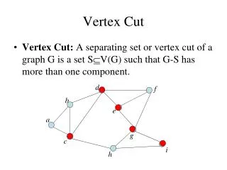
The Idea The incoming ions have an energy component in the X direction perpendicular to the sampling aperture EI and an energy component in the Y direction EII parallel to the sampling aperture Incoming ion with angleα EII EI α G1 G2 G3 C
Variable Aspect Ratio The aspect ratio determines if the EIIenergy component is such that the ion gets collected at the aperture electrodes or passes through the apertures for detection at the collector of the RFEA. Ion not collected Ion collected L L
Variable Aspect Ratio Using a Variable Bias The electric field applied in the EI direction determines if the EII energy component is such that the ion gets collected at the aperture electrodes or passes through the apertures for detection at the collector of the RFEA. Ion not collected Ion collected E Vangle L L
Aperture Between Grid 2 and Grid 3 Incoming ion with angleα EII EI α G1 G2 Vangle G3 C
Theory • The RFEA is designed to have electric fields in the X direction only, it is a planar system with all grids parallel to each other. • The discriminator potential at G2 is used to separate ions with different energy and acts only on the EIcomponent of the incoming ion. • The EIIcomponent of the ion energy is unaffected by the electric fields inside the sensor. • At any location inside the sensor the EII component of the ion energy is identical to the EII energy component of the ion as it entered the sensor through the sampling aperture. • By varying the potential difference between G2 and G3, Vangle the acceptance angle for which ions can enter the sensor is varied.
Discussion • The incoming ion arrives at the surface of G1 at an angle α • Based on positive voltage bias at G2 (w.r.t. G1) the ion decelerates and loses perpendicular energy component EIand reaches G2 at a different angle β • Due to negative voltage bias at G3 (w.r.t. G2) the ion accelerates and gains perpendicular energy componenet EIand reaches G3 with different angle ɤ. EII Incoming ion with angleα α EI G1 EII Ion with angleβ Deceleration EI β G2 EII Ion with angleɤ ɤ Acceleration EI G3 C
Concept • Tan(ɤ) = EII / EI • The ion will be collected at C only if Tan(ɤ) < 2a / L • No ion will be collected at C if Tan(ɤ) > 2a / L 2a G2 EII L ɤ EI G3 C
Concept • Tan (ɤ) = 1/r x Tan (β) • r = ratio of potential difference b/w G2 & G3 and G2 potential • By varying r, acceptance angle ɤ can be varied
Results EII ɤ1 EI ɤ2 Current Derivative ɤ3 ɤ4 ɤ1 ɤ2 ɤ3 ɤ4 ɤ5 ɤ6 Angle ɤ5 ɤ6 ɤ1 > ɤ2 > ɤ3 > ɤ4 > ɤ5 > ɤ6
Ion Angle Distribution • The discriminator grid G2 selects the energy window for ion detection. • At each energy selected the potential difference b/w G2 and G3 is swept through the various ion angles. • Current is collected at each set of angles • The current derivative shows the ion angle distribution
Ion Angle Distribution Ion Angle Measurement in CCP plasma 2.50E-07 2.00E-07 1.50E-07 1.00E-07 5.00E-08 0.00E+00 0 eV 10 eV 20 eV 30 eV 40 eV 50 eV -5.00E-08 0 degrees 3 degrees 6 degrees
Ion Angle Distribution average over 18 to 30eV 8.00E-08 7.00E-08 6.00E-08 5.00E-08 4.00E-08 3.00E-08 2.00E-08 1.00E-08 0.00E+00 9 degrees 0 degrees 6 degrees 12 degrees 15 degrees 18 degrees
Summary Angle is determined by ratio of EI and EII Collected current is reduced when high angle ions cross the aperture Varying aperture aspect ratio will vary collected ion current. Effective aspect ratio can be changed by applying Vangle to aperture. Collected current becomes a function of Vangle depending on ion angular distribution entering Semion. Derivative of ion current as a function of Vanglegives Ion Anglular Distribtuion function. Angle resolution 3 degrees over range 0 to 45 degrees