Download

1 / 115
1.19k likes | 1.45k Views
The Verilog Hardware Description Language. Professor Don Thomas Carnegie Mellon University (CMU) thomas@ece.cmu.edu http://www.ece.cmu.edu/~thomas

E N D
The Verilog Hardware Description Language Professor Don Thomas Carnegie Mellon University (CMU) thomas@ece.cmu.edu http://www.ece.cmu.edu/~thomas This is not one cohesive presentation on Verilog. The slides contained here are collected from different CMU classes at various academic levels. These slides are provided as an alternate aid to learning the language. You may find them helpful. Send bug reports to the above address — there are some! The Verilog Hardware Description Language, Fifth Edition is available from Kluwer Academic Publishers, http://www.wkap.com. Phone: 781-871-6600. Use or reproduction of the information provided in this file for commercial gain is strictly prohibited. Explicit permission is given for the reproduction and use of this information in an instructional setting.
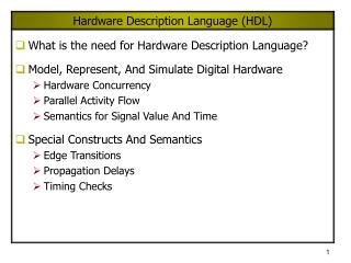
a f b sel Representation: Structural Models • Structural models • Are built from gate primitives and/or other modules • They describe the circuit using logic gates — much as you would see in an implementation of a circuit. • Identify: • Gate instances, wire names, delay from a or b to f. • This is a multiplexor — it selects one of n inputs (2 here) and passes it on to the output module mux (output f, input a, b, sel); and #5 g1 (f1, a, nsel), g2 (f2, b, sel); or #5 g3 (f, f1, f2); not g4 (nsel, sel); endmodule f = a • sel’ + b • sel
Representation: Gate-Level Models • Need to model the gate’s: • Function • Delay • Function • Generally, HDLs have built-in gate-level primitives • Verilog has NAND, NOR, AND, OR, XOR, XNOR, BUF, NOT, and some others • The gates operate on input values producing an output value • typical Verilog gate instantiation is: and #delay instance-name (out, in1, in2, in3, …); and #5 g1 (f1, a, nsel); “many” optional a comma here let’s you list other instance names and their port lists.
Four-Valued Logic • Verilog Logic Values • The underlying data representation allows for any bit to have one of four values • 1, 0, x (unknown), z (high impedance) • x — one of: 1, 0, z, or in the state of change • z — the high impedance output of a tri-state gate. • What basis do these have in reality? • 0, 1 … no question • z … A tri-state gate drives either a zero or one on its output…and if it’s not doing that, its output is high impedance (z). Tri-state gates are real devices and z is a real electrical affect. • x … not a real value. There is no real gate that drives an x on to a wire. x is used as a debugging aid. x means the simulator can’t determine the answer and so maybe you should worry! All values in a simulation start as x. • BTW … • Verilog keeps track of more values than these in some situations.
A B Input B Nand 0 1 x z 0 1 1 1 1 1 1 0 x x x 1 x x x z 1 x x x A 4-valued truth table for a Nand gate with two inputs Input A Four-Valued Logic • Logic with multi-level logic values • Logic with these four values make sense • Nand anything with a 0, and you get a 1. This includes having an x or z on the other input. That’s the nature of the nand gate • Nand two x’s and you get an x — makes sense! • Note: z treated as an x on input. Their rows and columns are the same • If you forget to connect an input … it will be seen as an z. • At the start of simulation, everything is an x.
Concurrent activity • Do these two evaluations happen at the same time? • Yes and No! • Yes … • They happen at the same simulated (or virtual) time • After all, the time when they occur is 27 • No … • We all know the processor is only doing one thing at any given time • So, which is done first? • That’s undefined. We can’t assume anything except that the order is arbitrary. Eval g2, g3 Yes and No!
Concurrent Activity • The point is • In the real implementation, all activity will be concurrent • Thus the simulator models the elements of the system as being concurrent in simulated time • The simulator stands on its head trying to do this! • Thus, • Even though the simulator executes each element of the design one at a time … • … we’ll call it concurrent
Delay • Transportdelay— input to output delay • “nand #35 (f1, a, b, c);” #35 is the transport delay • What if the input changes during that time? • i.e. how wide must an input spike be to affect the output. • Think of the gate as having inertia. — The input change must be present long enough to get the output to change. (That “long enough” time is called inertial delay) • in Verilog, this time is equal to the transport delay a a c b c b pulse too small, no output change — transport delay a c b
Let’s build a wider 2-bit mux • Build a 2-bit 2:1 mux • OK, let’s put two 1-bit 2:1 muxes in the same module with a common select line • What would it look like? a0 f0 b0 a f b a1 f1 b1 sel sel
Reuse! • Reuse of smaller objects • Can we use the mux module that we already designed? • A big idea — instantiation • Modules and primitive gates can be instantiated — copied — to many sites in a design • Previously, two ANDs, one OR, and a NOT gate were instantiated into module mux • Now we instantiate two copies of module mux into module wideMux module wideMux (f1, f0, a1, a0, b1, b0, sel); input a1, a0, b1, b0, sel; output f1, f0; mux bit1 (f1, a1, b1, sel), bit0 (f0, a0, b0, sel); endmodule Instantiate two mux modules, name them, and specify connections (the order is important).
Instantiation — Copies • Modules and gate primitives are instantiated == copied • Note the word “copies” • The copies (also called instances) share the module (or primitive) definition • If we ever change a module definition, the copies will all change too • However, the internal entities (gate names, internal port names, and other things to come) are all private, separate copies • Don’t think of module instantiations as subroutines that are called • They are copies — there are 2 mux modules in wideMux with a total of: ______ AND gates, ______ OR gates, ______ Not gates 4 2 2
Why is this cool? • In Verilog • “Primitive” gates are predefined (NAND, NOR, …) • Other modules are built by instantiating these gates • Other modules are built by instantiating other modules, … • The design hierarchy of modules is built using instantiation • Bigger modules of useful functionality are defined • You can then design with these bigger modules • You can reuse modules that you’ve already built and tested • You can hide the detail — why show a bunch of gates and their interconnection when you know it’s a mux! • Instantiation & hierarchy control complexity. • No one designs 1M+ random gates — they use hierarchy. • What are the software analogies?
How to wire modules together • Real designs have many modules and gates module putTogether (); wire w1, w2, w3, w4; bbb lucy (w1, w2, w3, w4); aaa ricky (w3, w2, w1); … what happens when out1 is set to 1? module bbb (i1, i2, o1, clk); input i1, i2, clk; output o1; xor (o1, i2, …); … module aaa (in1, out1, out2); input in1; output out1, out2; … nand #2 (out1, in1, b); nand #6 (out2, in1, b); … Each module has it’s own namespace. Wires connect elements of namespaces.
Implicit wires • How come there were no wires declared in some of these modules? • Gate instantiations implicitly declare wires for their outputs. • Allother connections must be explicitly declared as wires — for instance, connections between module ports • Output and input declarations are wires module mux (output f, input a, b, sel); and #5 g1 (f1, a, nsel), g2 (f2, b, sel); or #5 g3 (f, f1, f2); not g4 (nsel, sel); endmodule module putTogether (); wire w1, w2, w3, w4; mux inst1 (w1, w2, w3, w4); aaa duh (w3, w2, w1); … wires explicitly declared wires implicitly declared (f1, f2, nsel)
How to build and test a module • Construct a “test bench” for your design • Develop your hierarchical system within a module that has input and output ports (called “design” here) • Develop a separate module to generate tests for the module (“test”) • Connect these together within another module (“testbench”) module design (a, b, c); input a, b; output c; … module testbench (); wire l, m, n; design d (l, m, n); test t (l, m); initial begin //monitor and display … module test (q, r); output q, r; initial begin //drive the outputs with signals …
Another view of this • 3 chunks of Verilog, one for each of: TESTBENCH is the final piece of hardware which connects DESIGN with TEST so the inputs generated go to the thing you want to test... Your hardware called DESIGN Another module, called TEST, to generate interesting inputs
An Example Module testAdd generated inputs for module halfAdd and displayed changes. Module halfAdd was the design module testAdd(a, b, sum, cOut); input sum, cOut; output a, b; reg a, b; initial begin $monitor ($time,, “a=%b, b=%b, sum=%b, cOut=%b”, a, b, sum, cOut); a = 0; b = 0; #10 b = 1; #10 a = 1; #10 b = 0; #10 $finish; end endmodule module tBench; wire su, co, a, b; halfAdd ad(su, co, a, b); testAdd tb(a, b, su, co); endmodule module halfAdd (sum, cOut, a, b); output sum, cOut; input a, b; xor #2 (sum, a, b); and #2 (cOut, a, b); endmodule
The test module • It’s the test generator • $monitor • prints its string when executed. • after that, the string is printed when one of the listed values changes. • only one monitor can be active at any time • prints at end of current simulation time • Function of this tester • at time zero, print values and set a=b=0 • after 10 time units, set b=1 • after another 10, set a=1 • after another 10 set b=0 • then another 10 and finish module testAdd(a, b, sum, cOut); input sum, cOut; output a, b; reg a, b; initial begin $monitor ($time,, “a=%b, b=%b, sum=%b, cOut=%b”, a, b, sum, cOut); a = 0; b = 0; #10 b = 1; #10 a = 1; #10 b = 0; #10 $finish; end endmodule
Another version of a test module module testAdd(test, sum, cOut); input sum, cOut; output [1:0] test; reg [1:0] test; initial begin $monitor ($time,, "test=%b, sum=%b, cOut=%b", test, sum, cOut); test = 0; #10 test = test + 1; #10 test = test + 1; #10 test = test + 1; #10 $finish; end endmodule • Multi-bit “thingies” • test is a two-bit register and output • It acts as a two-bit number (counts 00-01-10-11-00…) • Module tBench needs to connect it correctly — mod halfAdd has 1-bit ports. module tBench; wire su, co; wire [1:0] t; halfAdd ad(su, co, t[1], t[0]); testAdd tb(t, su, co); endmodule Connects bit 0 or wire t to this port (b of the module halfAdder)
Another version of testAdd module testAdd(test, sum, cOut); input sum, cOut; output [1:0] test; reg [1:0] test; initial begin $monitor ($time,, "test=%b, sum=%b, cOut=%b", test, sum, cOut); for (test = 0; test < 3; test = test + 1) #10; #10 $finish; end endmodule • Other procedural statements • You can use “for”, “while”, “if-then-else” and others here. • This makes it easier to write if you have lots of input bits. module tBench; wire su, co; wire [1:0] t; halfAdd ad(su, co, t[1], t[0]); testAdd tb(t, su, co); endmodule hmm… “<3” … ?
Structural vs Behavioral Models • Structural model • Just specifies primitive gates and wires • i.e., the structure of a logical netlist • You basically know how to do this now. • Behavioral model • More like a procedure in a programming language • Still specify a module in Verilog with inputs and outputs... • ...but inside the module you write code to tell what you want to have happen, NOT what gates to connect to make it happen • i.e., you specify the behavior you want, not the structure to do it • Why use behavioral models • For testbench modules to test structural designs • For high-level specs to drive logic synthesis tools
How do behavioral models fit in? • How do they work with the event list and scheduler? • Initial (and always) begin executing at time 0 in arbitrary order • They execute until they come to a “#delay” operator • They then suspend, putting themselves in the event list 10 time units in the future (for the case at the right) • At 10 time units in the future, they resume executing where they left off. • Some details omitted • ...more to come module testAdd(a, b, sum, cOut); input sum, cOut; output a, b; reg a, b; initial begin $monitor ($time,, “a=%b, b=%b, sum=%b, cOut=%b”, a, b, sum, cOut); a = 0; b = 0; #10 b = 1; #10 a = 1; #10 b = 0; #10 $finish; end endmodule
1 a 0 1 b 0 1 out 0 0 10 18 Two initial statements? … initial begin a = 0; b = 0; #5 b = 1; #13 a = 1; end … initial begin out = 1; #10 out = 0; #8 out = 1; end … • Things to note • Which initial statement starts first? • What are the values of a, b, and out when the simulation starts? • These appear to be executing concurrently (at the same time). Are they? arbitrary x Yes, in simulated time
Other things you can do • More than modeling hardware • $monitor — give it a list of variables. When one of them changes, it prints the information. Can only have one of these active at a time. e.g. … • $monitor ($time,,, “a=%b, b=%b, sum=%b, cOut=%b”,a, b, sum, cOut); • The above will print: 2 a=0, b=0, sum=0, cOut=0<return> • $display() — sort of like printf() in C • $display (“Hello, world — %h”, hexvalue) extra commas print spaces %b is binary (also, %h, %d and others) What if what you print has the value x or z? newline automatically included display contents of data item called “hexvalue” using hex digits (0-9,A-F)
Technology Mapping One Modern Design Methodology always mumble mumble blah blah gates, gates, gates, … Synthesis Synthesizable Verilog Place and Route LE 1 LE 2 Logic Elements in FPGA Chip
What’s a Logic Element (LE) A mux selects which element of memory to send to output • Arbitrary programmable Boolean function of K inputs • K=4 in our particular example. Usually see K=3, 4, 5 in real FPGAs • It has a memory — you download to the memory to program the device • You also program connections between these Logical Elements • Synthesis tool partitions logic into groups of 5-input functions Really just a 1-bit memory
What do we mean by “Synthesis”? • Logic synthesis • A program that “designs” logic from abstract descriptions of the logic • takes constraints (e.g. size, speed) • uses a library (e.g. 3-input gates) • How? • You write an “abstract” Verilog description of the logic • The synthesis tool provides alternative implementations constraints Verilog blah blah blah synthesis or … library
a b f c An example • What’s cool? • You type the left, synthesis gives you the gates • It used a different library than you did. (2-input gates only) • One description suffices for a variety of alternate implementations! • ... but this assumes you know a gate level implementation — that’s not an “abstract” Verilog description. module gate (output f input a, b, c); and A (a1, a, b, c), B (a2, a, ~b, ~c), C (a3, ~a, o1); or D (o1, b, c), E (f, a1, a2, a3); endmodule
Combinational Logic A B F C What Do We Want Here…? • Goal • To specify a combination ckt, inputs->outputs… • … in a form of Verilog that synthesis tools will correctly read • … and then use to make the right logic • And... • We know the function we want, and can specify in C-like form... • … but we don’t now the exact gates (nor logic elements); we want the tool to figure this out.
Behavioral Modeling • Procedural statements are used • Statements using “always” Verilog construct • Can specify both combinational and sequential circuits • Normally don’t think of procedural stuff as “logic” • They look like C: mix of ifs, case statements, assignments … • … but there is a semantic interpretation to put on them to allow them to be used for simulation and synthesis (giving equivalent results) • Current technology • You can do combinational (and later, sequential) design • Sizable designs can take hours … days … to run • Companies pay $50K - 80K per copy for such software • This ain’t shrink-wrap software! • The software we use is more like $15-20K
Statement Looks like Starts How it works Use in Synthesis? initial begin … end No, used as testbench Execute once and stop initial Starts when simulation starts … in arbitrary order always begin … end Continually loop—while (power on)do statements; Yes, used in synthesis always Behavioral Constructs • Behavioral descriptions are introduced by initial and always statements • Points: • They all execute concurrently • They contain procedural statements like if-then-else, case, loops, functions, …
Statements, Registers and Wires Multi-bit registers and wires • Registers • Define storage, can be 1-bit or more • Can only be changed by assigning value to them on the left-hand side of a behavioral expression. • Wires (actually “nets”) • Electrically connect things together • Can be used on the right-hand side of an expression • Thus we can tie primitive gates and behavioral blocks together! • Statements • left-hand side = right-hand side • left-hand side must be a register • Four-valued logic Logic with registers and wires module silly (input [3:0] q, r); reg [3:0] a, b; always begin … a = (b & r) | q; … q = b; … end endmodule Can’t do — why?
Behavioral Statements • if-then-else • What you would expect, except that it’s doing 4-valued logic. 1 is interpreted as True; 0, x, and z are interpreted as False • case • What you would expect, except that it’s doing 4-valued logic • If “selector” is 2 bits, there are 42 possible case-items to select between • There is no break statement — it is assumed. • Sized, 4-valued constants • The first number is the number of bits, the letter is the base of the following number that will be converted into the bits. 8’b00x0zx10 if (select == 1) f = in1; else f = in0; case (selector) 2’b00: a = b + c; 2’b01: q = r + s; 2’bx1: r = 5; default: r = 0; endcase assume f, a, q, and r are registers for this slide
Behavioral Statements • Loops • There are some restrictions on using these for synthesis • for this course — don’t. • They are mentioned here for use in test modules • Two main ones — for and while • Just like in C • There is also repeat and forever — see the book reg [4:0] testOutput, i; … for (i = 0; i < 15; i = i + 1) begin testOutput = i; #20; end reg [4:0] testOutput, i; … i = 0; while (i < 15) begin testOutput = i; #20 i = i + 1; end Important: Loops must have a delay operator (or as we’ll see later, an @ or wait(FALSE)). Otherwise, the simulator never stops executing them.
Concurrent Constructs • We already saw #delay • Others • @ … Waiting for a change in a value — used in synthesis • @ (var) w = 4; • This says wait for var to change from its current value. When it does, resume execution of the statement by setting w = 4. • Wait … Waiting for a value to be a certain level — not used in synthesis • wait (f == 0) q = 3; • This says that if f is equal to zero, then continue executing and set q = 3. • But if f is not equal to zero, then suspend execution until it does. When it does, this statement resumes by setting q = 3. • Why are these concurrent? • While one model waits for something, that something happens (concurrently) in another model
FAQs: behavioral model execution • How does an always or initial statement start • That just happens at the start of simulation — arbitrary order • Once executing, what stops it? • Executing either a #delay, @event, or wait(FALSE). • All always blocks need to have at least one of these. Otherwise, the simulator will never stop running the model — (it’s an infinite loop!)
More FAQs • How long will it stay stopped? • Until the condition that stopped it has been resolved • #delay … until the delay time has been reached • @(var) … until var changes • wait(var) … until var becomes TRUE • Does time pass when a behavioral model is executing? • No. The statements (if, case, etc) execute in zero time. • Time passes when the model stops for #, @, or wait. • Will an always stop looping? • No. But an initial will only execute once.
c f b Example of Logic Synthesized sel A Combinational Circuit • Using behavioral constructs • Logic for a simple MUX is specified procedurally here • This example is synthesizable Read this as follows: Wait for any change on sel, b, or c, then execute the begin-end block containing the if. Then wait for another change. module mux (output reg f, input sel, b, c); always @ (sel or b or c) begin if (sel == 1) f = b; else f = c; end endmodule This “if” functionally describes the MUX
c f b Huh? Is it really correct? • WWWWaaaaaiiiiiitttt a minute? • Where’s the register? The synthesis tool figures out that this is a combinational circuit. Therefore, it doesn’t need a register. The register is there as an “artifact” of the description — things on the left-hand side have to be registers. • How does it figure out that this is combinational? • The output is only a function of the inputs (and not of previous values) • Anytime an input changes, the output is re-evaluated • From outside the module, could you tell that there is a register in there? • Does the loop have state? ? module mux (output reg f, input sel, b, c); always @ (sel or b or c) begin if (sel == 1) f = b; else f = c; end endmodule
Synthesis Template • Using procedural statements in Verilog • Logic is specified in “always” statements (“Initial” statements are not allowed). • Each “always” statement turns into Boolean functions You have to declare the combinational outputs like this, for synthesis. i.e., tool needs to think you are putting these computed outputs someplace. module blah (output reg f, input a, b, c); always @ (a or b or c) begin stuff... stuff... stuff... end endmodule You have to list all the block’s inputs here in the “sensitivity list”. (*) also works! Actually do logic in here. There are a bunch of subtle rules to ensure that synthesis won’t mess this up... We’ll see how…
How? … A Few Definitions • There are some restrictions on specification • Input set of an “always” statement — the set of all variables that are used on the right-hand side of procedural assignments or in conditionals. i.e. anything “sourced”. • Sensitivity list of an “always” statement — the set of all names that appear in the event (“@”) list. module mux (output reg f, input sel, b, c); always @ (sel or b or c) begin if (sel == 1) f = b; else f = c; end endmodule The elements in these lists are: input: sel, b, c sensitivity: sel, b, c No coincidence here: a combinational circuit is sensitive to its inputs
More Definitions... • … • A control path of an “always” statement — a sequence of operations performed when executing the always statement • Combinational output of an “always” statement — a variable (or variables) assigned to in every control path What are they here... module mux (output reg f, input sel, b, c); always @ (sel or b or c) begin if (sel == 1) f = b; else f = c; end endmodule Control paths: through “then” and “else” of if statement Combinational output: f
The Basic Rules • The rules for specifying combinational logic using procedural statements • Every element of the input set must be in the sensitivity list • Thecombinational output must be assigned in every control path module mux (output reg f, input sel, b, c); always @ (sel or b or c) begin if (sel == 1) f = b; else f = c; end endmodule So, we’re saying that if any input changes, then the output is re-evaluated. — That’s the definition of combinational logic. Walking this narrow line allows you to specify and synthesize combinational logic
What If You Mess Up? • If you don’t follow the rules...? • Verilog assumes you are trying to do something clever with the timing • It’s legal, but it won’t be combinational • The rules for what it does make sense — but not yet for us. … you’re dead meat This says: as long as a==1, then f follows b. (i.e. when b changes, so does f.) But, when a==0, f remembers the old value of b. Combinational circuits don’t remember anything! module blah (output reg f, g; input a, b, c); always @ (a or b or c) begin if (a == 1) f = b; else g = c; end endmodule What’s wrong? f doesn’t appear in every control path in the always block (neither does g).
Typical Style • Your Verilog for combinational stuff will look like this: • Yes...it’s a pretty restricted subset of the language... module blah (<output names>, <input names>); output <output names>; input <input names>; reg <output names>; always @ (<names of all input vars>) begin < LHS = RHS assignments> < if ... else statements> < case statements > end endmodule
A Difficulty • Assigning in every control path • If the function is complex, you don’t know if you assigned to the outputs in every control path. • So, set all outputs to some known value (zero here) and write the code to set them to other values as needed. • Synthesis tools will figure it out, but try to write clearly. always @(coke or cola) begin if (coke) blah1 = 1; else if (cola > 2’b01) blah2 = coke; else if ( … … end always @(coke or cola) begin blah1 = 0; blah2 = 0; if (coke) blah1 = 1; else if (cola > 2’b01) blah2 = coke; else if ( … … end
Using a case statement • Truth table method • List each input combination • Assign to output(s) in each case item. • Concatenation • {a, b, c} concatenates a, b, and c together, considering them as a single item • Example a = 4’b0111 b = 6’b 1x0001 c = 2’bzx then {a, b, c} = 12’b01111x0001zx module fred (output reg f, input a, b, c); always @ (a or b or c) case ({a, b, c}) 3’b000: f = 1’b0; 3’b001: f = 1’b1; 3’b010: f = 1’b1; 3’b011: f = 1’b1; 3’b100: f = 1’b1; 3’b101: f = 1’b0; 3’b110: f = 1’b0; 3’b111: f = 1’b1; endcase endmodule Check the rules …
How about a Case Statement Ex? module fred (output reg f, input a, b, c); always @ (a or b or c) case ({a, b, c}) 3’b000: f = 1’b0; 3’b001: f = 1’b1; 3’b010: f = 1’b1; 3’b011: f = 1’b1; 3’b100: f = 1’b1; 3’b101: f = 1’b0; 3’b110: f = 1’b0; 3’b111: f = 1’b1; endcase endmodule check the rules… module fred (output reg f, input a, b, c); always @ (a or b or c) case ({a, b, c}) 3’b000: f = 1’b0; 3’b101: f = 1’b0; 3’b110: f = 1’b0; default: f = 1’b1; endcase endmodule Could put a function here too Important: every control path is specified x and z not considered in case enumeration!
a b f ~c Don’t Cares in Synthesis module caseExample( (output reg f, input a, b, c); always @ (a or b or c) case ({a, b, c}) 3’b001: f = 1’b1; 3’b010: f = 1’b1; 3’b011: f = 1’b1; 3’b100: f = 1’b1; 3’b111: f = 1’b1; 3’b110: f = 1’b0; default: f = 1’bx; endcase endmodule • Rules • You can’t say “if (a == 1’bx)…” — this has meaning in simulation, but not in synthesis. • However, an unknown x on the right-hand side will be interpreted as a don’t care. ab 00 01 11 10 c 0 1 0 x 1 1 1 1 1 x The inverse function was implemented; x’s taken as ones.
Alternatively… module fred1 (output reg f, input a, b, c); always @ (a or b or c) f = ~(a & b & ~c); endmodule • These aren’t quite equivalent to the previous slide…why? module fred3 (output reg f, input a, b, c); always @ (a or b or c) begin if (c ==0) f = a~&b; else f = 1’b1; end endmodule module fred2 (output reg f, input a, b, c); always @ (a or b or c) f = ~a | c | ~b; endmodule ab 00 01 11 10 c 0 1 0 x 1 1 1 1 1 x