Download
1 / 38
380 likes | 732 Views
Function of APU's. Provide power for the orbiter's three independent hydraulic systems. Each system provides hydraulic pressure to position hydraulic actuators for: Thrust vector control of the main engines by gimbaling the three SSMEs Actuation of various control valves on the SSMEs Movement of

E N D
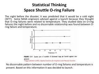
1. Failure Analyses of Space Shuttle APU Turbine Blades A Retrospective
2. Function of APU�s Provide power for the orbiter�s three independent hydraulic systems. Each system provides hydraulic pressure to position hydraulic actuators for:
Thrust vector control of the main engines by gimbaling the three SSMEs
Actuation of various control valves on the SSMEs
Movement of the orbiter aerosurfaces (elevons, body flap, rudder/speed brake)
Retraction of the external tank/orbiter 17-inch liquid oxygen and liquid hydrogen disconnect umbilicals within the orbiter at external tank jettison
Main/nose landing gear deployment (system 1)/(system 1 or 2)
Main landing gear brakes and anti-skid
Nose wheel steering (system 1 with backup from system 2).
3. APU Locations-Orbiter
4. APU Operation During a typical flight, the APUs are started 5 minutes before lift-off and operate through the Orbital Maneuvering System-1 (OMS-1) burn when hydraulic power is no longer required.
The APUs are basically inactive on orbit.
One APU is run briefly the day before deorbit to support the Flight Control Surface (FCS) checkout.
The APUs are restarted for the deorbit burn and entry. They are shut down shortly after landing.
5. APU Operation-Prelaunch Circ pumps run to flow hydraulic fluid through system
APU prestart at T - 6:15 minutes
APU start at T - 5 minutes
6. APU Operation-Ascent The HYD system provides hydraulic pressure to
Throttle and steer the orbiter main engines
Actuate the orbiter aerosurfaces
Retract the external tank/umbilical plates
All APUs are operated from T -5 minutes through the OMS-1. If there is no OMS-1 burn then APU shutdown comes after repositioning the main engines for orbit.
7. APU Operation-Entry The HYD system provides hydraulic pressure to
Actuate the orbiter aerosurfaces
Deploy the landing gear
Provide braking
Provide nosewheel steering
At D/O - 5 minutes, one APU is started to insure that an APU is operating through the entry flight phase.
At El - 13, the remaining two APUs are started and are operated through postlanding.
8. APU Chronology Initial design began in the early 1970�s
Reliability
Efficiency
Lightweight
Small footprint
Prototype testing in mid 1970�s.
Enterprise Flight Testing-1977
Initial flight Columbia STS-1, April 12, 1981
9. Orbiter APU
10. Cross Section of APU Turbine
11. APU Turbine Cross Section
12. APU Operational Details Each APU rated at 135 horsepower
Each APU weighs 88 Pounds
Turbine speed of 81,000 RPM
Up to Speed in 9.5 Seconds
Fuel for Gas Generator is Hydrazine
First stage gas temperature of 1700F
Two of the three APU�s must function for orbiter to function.
13. APU Fuel Hydrazine-N2H4
Liquid hydrazine is passed over a catalyst, Iridium, in the gas generator.
Decomposition of hydrazine produces ammonia, nitrogen and hydrogen.
Reaction is highly exothermic
14. Challenger Accident STS-51-L Challenger explodes 73 seconds after takeoff on January 28th 1986.
Space Shuttle flights halted while extensive investigation into accident and assessment of Shuttle program are conducted.
15. Post Challenger Presidential Commission Study The Commission concluded that there was a serious flaw in the decision making process leading up to the launch of flight 51-L. A well structured and managed system emphasizing safety would have flagged the rising doubts about the Solid Rocket Booster joint seal. Had these matters been clearly stated and emphasized in the flight readiness process in terms reflecting the views of most of the Thiokol engineers and at least some of the Marshall engineers, it seems likely that the launch of 51-L might not have occurred when it did.
16. Post Challenger Presidential Commission Study The Commission is troubled by what appears to be a propensity of management at Marshall to contain potentially serious problems and to attempt to resolve them internally rather than communicate them forward. This tendency is altogether at odds with the need for Marshall to function as part of a system working toward successful flight missions, interfacing and communicating with the other parts of the system that work to the same end.
17. NASA Post Challenger Systems Review On March 13, 1986, NASA initiated a complete review of all Space Shuttle program failure modes and effects analyses (FEMEA's) and associated critical item lists (CIL's). Each Space Shuttle project element and associated prime contractor is conducting separate comprehensive reviews which will culminate in a program-wide review with the Space Shuttle program have been assigned as formal members of each of these review teams. All Criticality 1 and 1R critical item waivers have been cancelled. The teams are required to reassess and resubmit waivers in categories recommended for continued program applicability. Items which cannot be revalidated will be redesigned, qualified, and certified for flight. All Criticality 2 and 3 CIL's are being reviewed for reacceptance and proper categorization. This activity will culminate in a comprehensive final review with NASA Headquarters beginning in March 1987.
18. NASA Concerns with APU Hydrazine Fuel
STS-9 (SpaceLab1)-Columbia-1983
Hydrazine fuel lines cracked on 2 APU�s while in-flight
Formed Hydrazine snowballs
Decomposed and exploded on landing at Edwards Air Force Base.
Ripped holes in aft fuselage of orbiter
Cracked Turbine Blades
Had been noted by engineers after first orbiter flights.
19. APU Turbine Blade Failure Analysis Investigation began in late 1986
Budgeted at $12MM
Identify root cause of blade cracking
Evaluate reliability per NASA standards.
If reliability is unacceptable, then redesign.
20. APU Turbine Blade Failure Analysis Companies Involved
NASA
Johnson Space Center, Houston, TX
Marshall Flight Science Center, Huntsville, AL
Rockwell International, Downey, CA
Rocketdyne, Los Angeles, CA
Sundstrand Aviation
Engineering, Rockford IL
Manufacturing, Denver, CO
Southwest Research Institute, San Antonio, TX
Rocket Research Company, Redmond, WA
21. APU Turbine Blade Failure Analysis Quarterly meeting with Sundstrand, Rockwell and NASA
Pre-meetings to support quarterly meetings
Specialists meetings between quarterly meetings
Personal computers in infancy
No internet and no Email
Photo were Polaroid
Presentations by overhead and 35mm slides
No videoconferencing
22. APU Turbine Blade Failure Analysis
Turbine disk details
Forged Rene 41 nickel-base alloy
Integral forged shaft
23. APU Turbine Blade Failure Analysis Turbine blade details
Blades integral with disk
Blade Passages ECM�d
Blades Polished by Extrudahone Process
Overhung Shroud Design
24. APU Turbine Blade Failure Analysis Turbine shroud details
Continuous shroud
Inconel 625
Shrunk fit
Electron Beam welded
25. APU Turbine Blade Failure Analysis
26. APU Turbine Blade Failure Analysis Transverse cracks noted in blades
Present on both 1st and 2nd stage sides
Variable length, up to 0.090� long
Approximately 3/8� from base of blade
Array of cracks observed
Longitudinal cracks noted at blade tips outboard of shroud
Cracks do Not Trend with Running Time or Start/Stop
27. APU Turbine Blade Failure Analysis
28. APU Turbine Blade Failure Analysis Fracture surfaces characterized as crystallographic
Origins near edges but not always at edges
No evidence of crack arrest marks
No evidence of fatigue striations
29. APU Turbine Blade Failure Analysis
Metallographic examination confirmed crystallographic transgranular fracture mode
White layer, after etching, observed along fracture and just in front of crack tip
Up to 0.0005� Deep
30. APU Turbine Blade Failure Analysis Results presented at first joint meeting
Hypotheses
High cycle fatigue due
Forced excitation
Resonance
Hydrogen embrittlement from decomposition of hydrazine
Brittle cracks
Nitriding due to decomposition of hydrazine
31. APU Turbine Blade Failure Analysis Further investigation
No white etching layer present on blade surfaces
Hardness indentations indicate white etching layer is softer than unaffected blade material
TEM examination revealed that white etching layer which void of gamma prime precipitates
32. APU Turbine Blade Failure Analysis SouthWest Research Institute investigation
Identified 3rd airfoil bending mode as cause of cracking
Frequency approximately 85 KHz
33. APU Turbine Blade Failure Analysis In Fall of 1987
Teardown of APU #3 on Atlantis revealed a partial blade separation
Flown on STS-51-J and STS-61-B
Transverse crack and longitudinal crack linked up
APU had accumulated 4.2 hours of operation
34. APU Turbine Blade Failure Analysis Nondestructive examination of all blades of all APU turbine disks flown in all Space Shuttles
Automated fluorescent Penetrant Inspection
Examined under stereomicroscope at 30X
Stereomicroscope modified for digital camera
Cracks identified and measured using NASA developed graphics software
Digital images stored on mainframe computer
35. APU Turbine Blade Failure Analysis Southwest Research Institute
Component flight reliability requirement
.999 Reliability, 95% Confidence
Weibull-Bayesian analysis
Critical crack size of 0.125�
Weibull shape parameter of �=6.683
Crack growth data from field returned APU turbine disks
Analysis concluded that NASA reliability requirement was satisfied with a limit of 25 hours of operation per disk.
36. Postscript Space Shuttles began flying again with STS-26, Discovery on September 29, 1988
Original design APU turbine disk used with life limit of 25 hours
New robust IAPU design initiated
FPI of existing fleet APU blades replaced by automated Eddy Current Inspection
Increased sensitivity
37. Postscript
IAPU design completed
Sharp blade edges eliminated
Full width shroud incorporated
Resonant condition eliminated
6% reduction in fuel consumption
IAPU flies on Endeavor, STS-47, September 1992
38. Postscript NASA continued to investigate alternative APU designs that did not use hydrazine
Electric
Hydrogen-oxygen