Download
1 / 49
500 likes | 634 Views
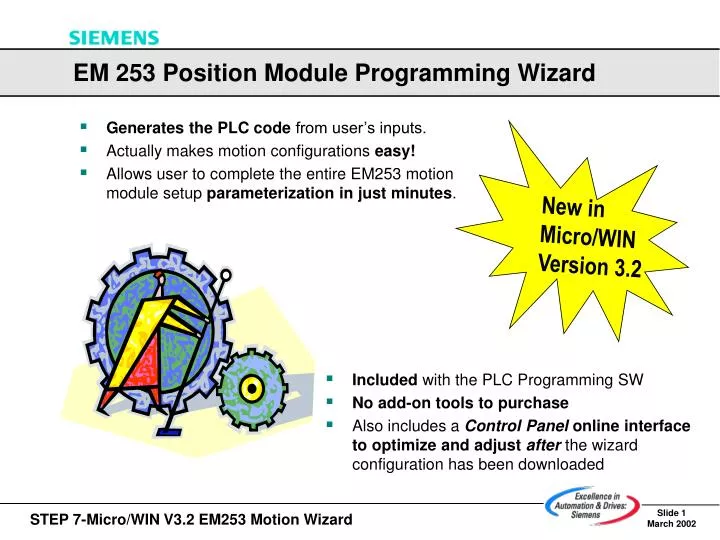
New in Micro/WIN Version 3.2. EM 253 Position Module Programming Wizard. Generates the PLC code from user’s inputs. Actually makes motion configurations easy! Allows user to complete the entire EM253 motion module setup parameterization in just minutes.

E N D
New in Micro/WIN Version 3.2 EM 253 Position Module Programming Wizard • Generates the PLC code from user’s inputs. • Actually makes motion configurations easy! • Allows user to complete the entire EM253 motion module setup parameterization in just minutes. • Included with the PLC Programming SW • No add-on tools to purchase • Also includes a Control Panel online interface to optimize and adjustafter the wizard configuration has been downloaded
Tutorial for Configuring the EM253 Position Module • PART 1:System Settings • PART 2:Machine (Drive) Data • PART 3:Setting Reference Point Search (RPS) Sequence • PART 4:Profile Definitions • PART 5:Wizard Results (Data Areas and PLC Code ) • PART 6:EM253 Control Panel • PART 7:EM253 Configuration FAQ’s
Launch the Position Control Wizard • Launch the wizard from the icon in the Tools menu • The following slides take you through each EM253 wizard screen, explaining all the input parameters, their meaning, and the significance of each one.
F1 PART 1: System Settings Select the EM 253 Configuration PLC on-boardPTO/PWM PLC withEM 253Module Press F1 for help onanyWizard screen.
PART 1: System Settings Intelligent Module Rack Position If connected to online PLC,Press ‘Read Modules’ button toautomaticallyread intelligent module’s rack position. Manuallysetting the Intelligent Module Rack Position (in offline configurations): Example: Digital I/O 1st EM253 Analog I/O 2nd EM253 CPU Physical Position: Intelligent Module Number: Intelligent Modules include: EM 241, EM 253 and EM277 CPU Digital I/O Analog I/O EM253 EM253
PART 1: System Settings Select a Measurement System A measurement system is selected by the user, based on theuser’s preference. • Engineering Unit Selections: • inch • foot • millimeter • centimeter • degree • radian • any user-defined unit The default ‘units’ are based on the project’s ‘Regional Settings’ from the Micro/WIN Options menu. • The measurement system,Engineering UnitsorNumber of Pulses,selected on this screen is used throughout the wizard configuration. • The motor’s Data Sheet specifies the pulses per revolution. • Specifying units is convenient because the wizard handles all conversions for the user.
EM253 STP RPS LMT - RPS STP LIM- LMT + LIM + PART 1: System Settings Advanced I/O Options (1 of 3) LED’s: Activation Level Settings Inputs: Module Reference Settings: High- a logic 1 will be read when current is flowing in the input. Low- a logic 1 will be read when there is no current flow in the input. Alogic 1 levelis always interpreted as meaning thelimit has been reached. The module LED’s will be ON if there is current flow to the corresponding input, regardless of the active level configured.
PART 1: System Settings Advanced I/O Options (2 of 3) Input Filter Time for EM inputs (applies to LMT+, LMT-, STP) Filter Time for the RPS input Selection Range: • 0.20 – 12.80 millisecond • ‘None’ is also an option Input Filter Timeis delay time. The input must remain at the new state for the duration of the delay time in order to be accepted as valid. Purpose:The filter rejects noise impulses and forces input lines to stabilize before the data is accepted.
PART 1: System Settings Advanced I/O Options (3 of 3) The Pulse Typeis determined by the nature of the device. Linear Rotary Positive Direction Negative Direction An estimated 90% of users will use devices with this default setting.
PART 2: Machine Data Set up how the H/W inputs will Respond • Choices for each response are: • Decelerated Stop. • Immediate Stop. • No action. (Ignore input) These settings should not be substituted for an Emergency Stop (E-Stop). Choices:Descriptions: Decelerated Stop : decelerates to a stop and indicates LIMIT reached (LIM activated). Immediate Stop : stops by terminating pulses and indicates LIMIT reached (LIM activated). No Action : ignores input condition.
MOST Important !!! PART 2: Machine Data Use the Motor’s Data Sheet Certain Motor parameters are vital in setting up the next wizard screens. You must gather information from the Motor’s Data Sheet. Data Sheet Example: Motor Speeds: Max. torque • Typically found as a waveform on the data sheet: • For MAX_SPEED, on the motor’s data sheet, find: • Maximum torque • Determine theMax.Torque for the applicationPick a range where application will most likely work. This is NOT the same as maximum motor torque. • Speed at which that torque can be achieved (This is the MAX_SPEED to input in wizard) • Max. torque for the Application • NOTE: • If it’s a guess: • The Curve Knee is good place to start. • Pick from a approx. range and experiment • For SS_SPEED, on the motor’s data sheet, find: • Start Speed (also called “Pull-in”) • Stop Speed (also called “Pull-out”) • SS_SPEED is the minimum of these 2 values. • Typically, a useful SS_SPEED value is 5% to 15% of • the MAX_SPEED value. Max. torque speed Max. torque speed for the application Pull-in: ~ 80 Step/sec. (pulses/sec) Click for More Details NOTICE: As load inertia increases, the curve drops.
MOST Important !!! PART 2: Machine Data Set Motor Speeds To achieve maximum resolution at higher speeds, range checking is enforced: the EM253 selects a time-base to work with based on the maximum speed. With this strategy, the EM253 calculates and enforces a minimum speed. • Notes about SS_SPEED: • iftoo high, motor can ‘stall’ or ‘overshoot’ • iftoo low, motor can ‘cog’. Start-Stop Speed(SS_SPEED) is the guaranteed speed at which motor can start and stop. It is the speed plus theapplication’s ‘load’ factored in. SS_SPEED value must be greater than the minimum speed displayed from your specification of MAX_SPEED. Click for More Details The SS_SPEED is a mandatory setting.
Achieved by constantly enabling the Jog command Achieved with a 1-shot Jog instruction - or- with one click on the Jog button PART 2: Machine Data Set JOG parameters (for manual debugging) Jog Commands are enabled from(1)the Control Panel or(2)an EM253 pre-defined profile or(3)a Micro/WIN Motion instruction (these are described in more detail in later slides). JOG_INCREMENTis the distance you want the tool to move with each JOG Command. JOG_SPEEDis the maximum speed that can be obtained while the JOG command remains active. When the JOG command is de-activated, the EM253 automatically executes a command that causes the tool to decelerate until it reaches STOP.
MOST Important !!! PART 2: Machine Data Set Acceleration & Deceleration Times ACCEL_TIME: Time required for the motor to accelerate from SS_SPEED to MAX_SPEED. DECEL_TIME: Time required for the motor to decelerate from MAX_SPEED to SS_SPEED Note About Defaults: 1 second default should work for most applications. Typically, motors can work with less than 1 second. MAIN POINT TO REMEMBER: The motor’s Acceleration & Deceleration times arestrictly determined by trial and error. Times set too short can cause the motor to stall.
MOST Important !!! PART 2: Machine Data Acceleration & Deceleration Times Data Sheets show a (theoretical) example: Practical Way to input the Values: • ‘THEORETICAL’ vs. ‘PRACTICAL’ • Theoretically, the values could be calculated (as on data sheet) • ‘Trial and Error’ approach is the efficient way of setting the values. • USE TRIAL & ERROR • Approximate values should be entered on the wizard once. Specifically, start with a large value in the wizard setting to get the application going. • During the start-up phase, adjust the values as needed with the EM253 Control Panel (EM253 Control Panel is explained later). • Optimize these settings for the application by gradually reducing the times until the motor starts to stall. How the values are used by EM253: Based on the wizard inputs for the times and motor speeds, the EM253 calculates the Accel and Decel rates (number of pulses to accomplish the target speed). Click for More Details
PART 2: Machine Data Set ‘Jerk’ Time parameters • Jerk timeprovides smoother motion control by reducing the “jolt” (rate of change) in acceleration and deceleration parts of the move profile. • Reducing “jerk” improves position tracking performance. • “Jerk” time is also known as “Jolt” or “S-Curve” profiling. • Jerk Time can only be applied to simple 1-step profiles. (Profiles are explained later). NOTE: A good first value for JERK_TIME is 40% of ACCEL_TIME.
PART 3: Setting RPS Sequence Reference Point TheReference Point(RP) is only for applications usingAbsolute moves(moves that are relative to a specified RP) If you select not to use the Reference Point, the wizard dialogs for setting RP will be skipped. In a subsequent wizard screen, the user will select a ‘Mode’ for the tool movements. Unlike all other modes, the Absolute ‘Mode’ is based on a Reference Point setting. Note: ‘Homing sequence’ is a term often used interchangeably with Reference Point.
RP Seek Direction RPS RP Approach Direction Active Work Zone LIMIT Active 1 2 3 4 PART 3: Setting RPS Sequence Reference Point Seek: A Working Example • Seek RPS Zone to the Right • Measure RPS Zone Width • Approach RP to the Right • 50% of the RPS Zone is in the Work Zone, RP is in its Middle Note: This is a working example of how a RP Seek would work in an application. As described on following slides, this is only one of many RP seek sequences available; the different RP seek sequences are selected depending on the specific application
Workspace Where's the Tool ??? - LMT + LMT RP Zero Position The tool is present, although it’s location is unknown RP Offset PART 3: Setting RPS Sequence How the RP (Reference Point) is used Wizard settings for RP are used in a ‘Seek Sequence’. A ‘Seek Sequence’ is executed (is command driven) when a tool abnormally stops or malfunctions (when the exact location of the tool is unknown). The EM253 uses pre-defined searches to locate the tool to a known position in the workspace. The tool is located according to a RP Seek Sequence that is selected by the user (the PLC programmer). The wizard allows the user to select the Seek Sequence that will fit best their application, and it enhances the optimization of the user’s system. Click for More Details
PART 3: Setting RPS Sequence Reference Point ‘Seek’ Parameters RP_FAST Speed RP_SLOW RP_SEEK_DIR Direction RP_APPR_DIR Click for More Details Purpose of inputs on this screen: RP_SLOW – search slows down as it approaches the target point, and will not miss it (~ SS_SPEED). RP_FAST – search speeds up to expedite the search (typically this will be 2/3 the MAX_SPEED) RP_SEEK_DIR – direction that the application’s searches generally move in most of the time; this avoids switching directions often, which would ultimately slow down the overall search. RP_APPR_DIR – same direction as the normal work cycle proceeds in; this reduces backlash and provides more accuracy
Workspace - LMT + LMT RP Offset Zero Position RP PART 3: Setting RPS Sequence Advanced RP Options RP Offset (RP_OFFSET) is at a fixed, constant location, at an exact distance from the zero position. Backlash compensationwould be used when a tool is not moved in the same direction ( not for constant back & forth motion). Note:When appropriately used, Backlash compensation allows the use of a lower cost equipment (such as worm gears).
PART 3: Setting RPS Sequence Setting a Reference Point Search (RPS) Sequence 4 possible Seek (Mode) Sequences: MODE 1:The reference point is where the RPS input goes active on the approach from the work zone side. MODE 2:The reference point is centered within the active region of the RPS input. MODE 3:The reference point is located outside the active region of the RPS input. MODE 4:The reference point is located within the active region of the RPS input. The graphic shown is dependent on your previous wizard inputs: (a)Seek Sequence (b) ‘Direction of RP Seek’ (c) RP_APPR_DIR ZP (Zero Pulse) input countis the number of pulses issued after the home search trigger condition is met. Note: There are 4 possible Reference Point (RP) definition. With RP_SEEK_DIR and RP_APPR_DIR settings, there are 16 different sequences.
A ‘Step’ is a fixed distance for a tool to be moved, including distance covered during acceleration & deceleration times. Speed Distance / Number of Pulses One ‘Step’ PART 4: Profile Definitions Setting the number of User Profiles • A Profile is created from a set of parameters associated with a tool’s movement. • A profile is shown graphically as a function of speed and distance (see the diagram) • You input the number of profiles to be defined for this EM253 project (25 is maximum profiles allowed) • This Q-memory area is used to trigger commands that get executed by the module. Note: The programmer defines number of profiles for the project on this screen. Parameters for each profile are specified on a subsequent screen.
PART 4: Profile Definitions Start address for the wizard configuration data • You input the starting PLC memory address of where the profile data will be placed into the PLC memory (34 bytes for each profile) -or- • Press ‘Suggest Address’ button and Micro/WIN inserts the start address of an unused, available area
(a.) 1-Step Profile (b.) 1-Step Profile The only thing changing will be Accel. & Decel. rates. At minimum, this profile requires the Wizard profile configuration to set the ‘type’. (c.) 4-Step Profile (d.) 4-Step Profile Different colors represent the different steps. Refer to the notes in figure (a.) PART 4: Profile Definitions Examples of ‘Workable’ Profiles These are not the only profiles allowed. There are many other combinations.
Desired ending position from the Zero Point. Desired ending position from the Starting Point. Zero Point Starting Point 0 (Zero Point) Absolute Position Relative Position Controlled by your program until another command (such as ‘Abort’) is issued RPS signals Stop Target Speed Single-speed Continuous Rotation Single-speed Continuous Rotation with Triggered stop. Target Speed with RPS Inactive Target Speed with RPS Inactive Two-speed Continuous Rotation PART 4: Profile Definitions Understanding the profile ‘Mode’ selections Click for More Details
PART 4: Profile Definitions Create Profile Definition(s) 1. Select a mode for this profile. 2.Input parameters to define the step: (a.) Target Speed (b.) Ending Position 4.Press to define another new step in the current profile. 3.Click ‘Plot Step’ button (Step appears in the window). 5.Repeat 1 – 4 for each step (up to 4 steps) in each profile. 6.Repeat entire process for each new profile definition (max. 25 profiles) You can assign a name to each profile. Note: Based on the programmer inputs for ‘Target Speed’ and ‘Ending Position’ for defining the step, the resulting, calculated units of measurement will be displayed (as read only field) beneath the input parameters.
PART 5: Wizard Results Completing the Wizard Configuration • The wizard screen now explains what changes will be made to your Micro/WIN program. • When you complete the wizard by clicking the ‘Finish’ prompt: (1) the indicated changes are made to your Micro/WIN project. (2) The instructions are added under the ‘Call Subroutines’ folder of the instruction tree. (3) A Symbol table containing EM253 project symbols is added to the project
MOST Important !!! MOST Important !!! PART 5: Wizard Results Summary : Your Inputs into Motion Wizard This is a review of the input fields on the wizard screens: System Settings • Intelligent Module Position in the PLC Rack • Select Measurement System & Engineering Units • Module Response to LIM+/- Switch & Stop Input • Motor Speed (Starting, Maximum, Jog) • Motor Acceleration & Deceleration Times • Reference Point Seek Speed & Direction • Advanced Reference Point settings (Optional button) • Reference Point Search Sequence • Number of Profiles & Address of QB Command Byte • V-memory Start Address of Data Block Locations • Profile Definitions (Mode and Steps for every profile) • Last Screen shows summary of EM253 project entries Machine Data Seek Reference Point Settings Profile Definition & Data Areas Finish
PART 5: Wizard Results Review : What the Motion Wizard Generates SBR’s for Motion Instructions are placed in the Micro/WIN Instruction tree under ‘Call Subroutines’: One Q byte location is set as the EM253 ‘Command Control’ Byte: Data Block values (V-memory): 60-BYTES IN DATA BLOCK (FOR MODULE CONFIGURATION SETTINGS) POS0_CTRL (SBR1) POS0_MAN (SBR2) POS0_RUN (SBR3) POS0_SRATE (SBR4) POS0_GOTO (SBR5) POS0_DIS (SBR6) POS0_LDOFF (SBR7) POS0_LDPOS (SBR8) POS0_RSEEK (SBR9) POS0_CLR (SBR10) POS0_CFG (SBR11) Q-MEMORY BYTE 40-BYTES FOR PROFILE #1 A Project Symbol Table containing EM253 Settings: (OPTIONAL) 40-BYTES FOR PROFILE #2 GLOBAL SYMBOL TABLE CONTAINING THE POSITION MODULE PARAMETERS . . . 40-BYTES FOR PROFILE X (MAX: X = 25) Each EM253 configuration created will place a set of instructions (one for ea. module in your rack). For example: EM253 configuration 1 = POS0_ … EM253 configuration 2 = POS1_ … EM253 configuration 3 = POS2_ … Etc. Multiple EM253 configurations are possible. Each configuration will have it’s own set of DB values.
POSx_CTRL Control POSx_RUN Run Profile POSx_MAN Manual Mode GOTO Enables and initializes the Position module. Ensures that your program calls this instruction every scan. Use SM0.0 (Always On) as the input for the EN parameter. Commands the Position Module to go to a desired location. Puts the EM253 module into manual mode. This allows the motor to be run at different speeds or to be jogged in a positive or negative direction. You can enable only one of the RUN, JOG_P, or JOG_N inputs at a time. Commands the Position module to execute the motion operation in a specific profile stored in the configuration/profile table. PART 5: Wizard Results Instruction Descriptions (1 / 3)
POSx_LDOFF Load Reference Point Offset POSx_LDPOS Load Position POSx_RSEEK Seek Ref Pt Position Initiates a reference point seek operation, using the search method in the configuration/ profile table. Change the current position value in the Position module to a new value. You can also use this instruction to establish a new zero position for any absolute move command. Establishes a new zero position that is at a different location from the reference point position. PART 5: Wizard Results Instruction Descriptions (2 / 3)
POSx_CFG Reload Configuration POSx_SRATE Set Rate POSx_DIS Turns DIS output of EM On or Off POSx_CLR Pulse CLR Output The POSx_DIS instruction turns the DIS output of the Position module on or off. This allows you to use the DIS output for disabling or enabling a motor controller. Commands the Position module to read the configuration block from the location specified by the configuration/profile table pointer. Commands the Position module to generate a 50-ms pulse on the CLR output. Commands the Position module to change the acceleration, deceleration, and jerk times. PART 5: Wizard Results Instruction Descriptions (3 / 3)
PART 6: Control Panel EM 253 Control Panel (for start-up & debugging) • Runs independently of the user’s program • Selected as separate icon under Tools • Verifies wiring of EM253 is correct • Verifies EM253 is configured correctly • Allows minor adjustments to be made to the EM253 configuration • Prompts user if adjustments should be made permanent to the EM253 configuration • PLC should be ONLINE and in STOP mode, to perform the commands or change parameter settings. NOTE: An online EM253 module is required to execute the Control Panel.
PART 6: Control Panel ‘Operation’ tab Select Module Command Module Status Manual Operation Profile Status
EM253 Step 3 Step 2 Step 4 Step 1 PART 6: Control Panel Profile & Module Status Profile Status Module Status Examine the individual profiles.
PART 6: Control Panel Select a Module Command List-box of 13 Module Commands • Each command selection is different: • Necessary fields and buttons are enabled. • Instructions for the selected command are displayed. Run a Motion Profile Enable Manual Operation Seek to a Reference Point (1) Type in a profile number, and (2) click Execute. EM253 runs that profile one time (includes all steps). Click Execute starts the EM command to search for a Ref. Point using the algorithm configured for the EM253. Use Manual controls to place the tool. Load Reference Point Offset Reload Current Position Activate/Deactivate DIS output (1) Use Manual controls to place the tool at a new Zero Position. (2) Click Execute to save this as the RP_OFFSET . Click Execute to activate the DIS output. (1) Type in the position to set, and (2) press Execute to initiate the move. Pulse the CLR output Teach a motion Profile Load Module Configuration Loads a new configuration by commanding the EM module to read the configuration block from the V memory. (1) After setting profile number and step, (2) use Jog buttons to position the tool, (3) then press Teach button to save it. Click Execute to pulse the CLR output. Move to An Absolute Position Move by a Relative Amount Reset the Command Interface Moves to a specified position at a target speed. Before using this command, you must have already established the zero position. Clears the command byte for the Position module and sets the Done bit. Move a specified distance from the current position at a target speed (Positive or Negative distance).
PART 6: Control Panel Manual Operation This portion of the screen changes depending on what ‘Module Command is selected. Used to reset, and set different values while command is running. Determines how fast the tool will move with manual operations. Used to toggle the EM253 between Start and Stop Determines whether tool moves backwards or forwards. Only possible in STOP mode. Hold down the Jog button to reach JOG_SPEED. Click once on Jog button for JOG_INCREMENT
PART 6: Control Panel ‘Configuration’ tab allows real-time user inputs Determines whether screen fields can be Edited or are Read-only Reference Point Settings Application Parameters If pressed, causes the screen values to be written to the PLC data block. NOTE: Upon exit of the Control Panel, the user is prompted about whether changes should be permanently written to the EM253 configuration.
All Error codes Are found in The S7-200 Systems Manual. PART 6: Control Panel ‘Diagnostics’ tab has Module Information Whenever Error(s) occur, the Diagnostics Tab flashes: “New Error In Module” This Error indicator is then visible from any screen in the Control Panel. Module Information • Displays information about EM253 such as: • - Position of EM in I/O Chain • - Module Type • - Firmware Version • Command Byte • Error Codes
PART 7: EM253 Configuration FAQ’s EM 253 Configuration FAQ’s (1/2) QUESTION:If user has already finished configuring the EM253 module with the wizard, how can subsequent changes be made to the configuration? ANSWER:Re-run the wizard, or use the EM253 control panel. QUESTION:Can the PLC programmer program the EM253 without using the EM253 wizard? ANSWER:Yes, although this is not recommended because of the number of required data fields. QUESTION:If user has selected engineering units, can the user change to different engineering units or to pulses/revolutions later in the configuration? ANSWER:Yes, although no conversion will take place. However, on a re-edit of a configuration, the user cannot change between engineering units and pulses. QUESTION:If user has more than one EM253 module, can the wizard be run for each module? ANSWER:Yes. The user can run the wizard multiple times as long as sufficient memory is available. The programmer must set the start addresses so that multiple EM253 configurations do not overwrite one another. QUESTION:A user has two EM253 modules and the user needs to copy the first configuration in order to make minor modification for the second EM253. How can the configuration be copied? ANSWER:When existing configurations are present, the wizard can move a configuration to another slot. No copy is provided. QUESTION:Can a PLC use the on-board PTO/PWM and the EM253 at the same time? ANSWER:Yes. The wizard is run twice (once for the PLC’s onboard PTO and once for EM253). QUESTION:Can the Accel. and/or Decel. Times be changed ‘on the fly’? How? ANSWER: Yes. From the EM523 Control Panel, or by using the POSx_SRATE motion instruction.
PART 7: EM253 Configuration FAQ’s EM 253 Configuration FAQ’s (2/2) QUESTION:Does the EM253 support ‘micro-stepping’? ANSWER:Yes, up to the maximum speed of the module (200 KHz). To configure it in the wizard, increase the pulses required for one revolution. QUESTION:Can each profile have a different mode? ANSWER:Yes. QUESTION:If I have 2 profiles that need to be run back-to-back, will there be a delay between the 2 profiles? ANSWER:Yes, since it must stop & then start back up; length depends on: (1) whether the profile is ‘buffered’ and (2) PLC scan time. QUESTION:Is it possible to enter a RP (Ref. Point) without a “home sequence”? ANSWER:Yes. An instruction, POSx_LDPOS, is available for doing this. QUESTION:Can I synchronize 3 devices in one system (PLC, motion data, position counter) ? ANSWER:Yes. This would be done with the PLC logic (not done automatically with the EM253). QUESTION:Can I use an HMI to control or monitor my motion module status? ANSWER:Yes. Use HMI to control memory area associated with the EM253 inputs and outputs, or the motion instructions’ inputs and outputs. QUESTION:Can I link the execution of more than 1 profile without stopping? ANSWER:No. The EM253 must stop after each profile. A profile always starts with motor stopped, and always ends with the motor stopped. QUESTION:Where can I find out more details and information about configuring the EM253 ? ANSWER:The new S7-200 Systems Manual (Chapter 9) covers the EM253 Position Module (Manual Order No.: 6ES7 298--8FA22--8BH0)
The End. The End. Thanks for your Attention. For further information about the EM253: Refer to the S7-200 Systems Manual, Chapter 9
Use the Motor’s Data Sheet – More Details Selection of the MAX_SPEED parameters is not always easy. Users typically do not know what the ‘Torque for the application’ is going to be. If you have no idea, then guess by picking a value near on the waveform’s ‘knee’, and then adjust it later. “MOST IMPORTANT” is shown in bold on the slides that discuss (1) Motor speeds and (2) Acceleration/Deceleration times. Why? These parameters are most critical in getting the EM253 set up to work properly. In general, if a user can set these parameters with reasonable data for his/her application, then the EM253 will basically work with the application. All other parameters are also important in getting a system to work optimally. However, in the initial start up phase, the parameters (marked as ‘MOST IMPORTANT’) are most critical. If customer has a motor whose data sheet parameters are not sufficient for the what the application needs, then the customer probably needs a bigger motor. If the “start-speed” is given in ‘steps/sec’, and user is using units other than pulses/sec, then user will need to convert from pulses/sec to units, such as inches. Example: If 1000 pulses = 1 inch Then 80 step/second will be 80/1000 inches/second Return To Slides
Set Motor Speeds – More Details • The SS_SPEED is mandatory. • All other calculations (In subsequent screens like when specifying Profiles, Jog parameters, Accel/Decel parameters, etc.) the SS_SPEED is used by the module in calculating and making the programmed moves. • When you set MAX value, the EM253 selects the range for you as seen in the MIN_SPEED, which is a read-only field. It means that the pulse rate will not go any lower than the calculated MIN_SPEED. • SS_SPEED cannot be lower than MIN_SPEED, and this is enforced by a range check performed by the wizard. • The EM253 module supports the following ranges: • 12 PPS to 2K PPS • 60 PPS to 10K PPS • 300 PPS to 50K PPS • 1200 PPS to 200K PPS Return To Slides
Acceleration & Deceleration Times – More Details • It is theoretically possible to calculate the Acceleration/Deceleration times from inertia, friction torque, etc. as shown on a motor’s data sheet. • However, 90%-100 % of average users are not able to obtain or calculate these values. (It is too scientific, data such as ‘inertia’ is unknown, etc. ) • This is where the Micro/WIN Wizard & Control Panel makes it easy for the users!!! • As stated on the slide, the practical way to set up the Acceleration/Deceleration times is with “trial and error” in the initial set up: • Start with a large value. • After you get the application going, start gradually reducing the time until motor stalls. Return To Slides
How the RP (Reference Point) is used – More Details • Absolute Move - A position move relative from a specified reference point or "zero position." • Relative Move - (incremental move) where the position move is relative from the current position. The two settings (INITIAL & APPROACH) can be set opposite. For instance, ‘initial’ direction can be opposite the ‘approach’ direction. • Relative Move - (incremental move) where the position move is relative from the current position. • NOTE: The slides show ‘linear’ motion (‘rotary’ motion is also possible with EM253) • WORKSAPCE AREA:EM253 applications take place within aWorkspace area. • BOUNDARY LIMITS:The workspace has boundaryLIMITSon each side. • The LIM boundaries are typically sensor devices that provide inputs to the EM253. • The application reacts to LIM inputs based on the LIM responses. • ABSOLUTE MOVES: • To perform anAbsolute Move, the important positions are: • A known Tool Position (not shown) that can be in or out of the workspace area. • A Reference Point (RP) is used as the target of the tool’s movement (for initialization). • A Zero Point (ZP) is at a fixed, constant location • Why does seeking need to be time efficient? • Seeking is typically used between an application’s transition between builds, or at the beginning of work cycles, etc. The seek sequence reduces time and effort needed to place the work tool in the correct starting position. Otherwise, manual intervention to move the tool could be required, which would require extra man power and would cost more time. Return To Slides
Reference Point ‘Seek’ Parameters – More Details The tool will start the seek at a faster speed because seeking needs to be time efficient. This is calledRP_FAST. It is used in positioning the tool (As Quickly As Possible) near the RP. Since the tool can only stop at certain speeds, it must be going that speed when it reaches the RP. This is called theRP_SLOW(NOTE: This speed must be less than SS_SPEED). The two settings (INITIAL & APPROACH) can be set opposite. For instance, initial direction can be opposite the approach direction. SEEK BEGINS with: RP_SEEK_DIR - For each seek, will the initial seek direction be positive (right) or negative (left)? RP_FAST – (consider motor size & SS_SPEED) How fast should seek be set? During the SEEK : (1) The tool begins to move. Tool will move towards the RP -or- towards a LIM, depending on set direction. (2) If tool reaches a LIM, tool movement reverses and continues in the other direction towards the RP. (3) Tool speed is reduced (to the settings below) as it approaches the RP and prepares to stop. SEEK FINISHES with: RP_APPR_DIR - will the seek direction be positive (right) or negative (left)? RP_SLOW – (consider motor size & SS_SPEED) how fast should seek be set? APPLICATION NOTE:Normally, with linear moves, the application direction and seek direction will be opposite. With rotary moves, they will be the same. Return To Slides
The profile ‘Mode’ selections – More Details Execution of commands shall cause the module to perform the motion operation specified in the MODE field of the Profile Block indicated by the command_code portion of the command. The specifications for Interactive Block motion operations are not cached, so they are read each time that the module receives this command. In absolute position mode the motion profile block shall define from one to four steps with each step containing both the position (POS) and speed (SPD) that describes the move segment. The POS specification represents an absolute location, which is based on the location designated as reference point. The direction of movement is determined by the relationship between the current position and the position of the first step in the profile. In a multi-step move, a reversal of direction of travel shall be prohibited and shall result in an error condition being reported. In relative position mode the motion profile block shall define from one to four steps with each step containing both the position (POS) and the speed (SPD) that describes the move segment. The sign of the position value (POS) shall determine the direction of the movement. In a multi-step move, a reversal of direction of travel shall be prohibited and shall result in the reporting of an error condition. In the single-speed, continuous speed modes, the position (POS) specification shall be ignored and the module shall accelerate to the speed specified in the SPD field of the first step. One Mode is used for positive rotation and the other mode is used for negative rotation. In the single-speed, continuous speed modes with triggered stop, the module shall accelerate to the speed specified in the SPD field of the first step. If and when the RPS input becomes active, movement shall stop after completing the distance specified in the POS field of the first step. One Mode is used for positive rotation and the other mode is used for negative rotation. In two-speed, continuous speed modes the binary value of the RPS input selects one of two continuous speed values as specified by the first two steps in the profile block. One Mode is used for positive rotation and the other mode is used for negative rotation. The SPD controls the speed of movement. The POS values shall be ignored in this mode. The following table defines the relationship between the inputs and the step within the profile block. Return To Slides