Download
1 / 19
190 likes | 370 Views
Control of Wind Turbine Flows using Vortex Generators Clara Velte Martin O. L. Hansen Dalibor Cavar Knud Erik Meyer MEK/Section of Fluid Mechanics DTU. Vortex generators (VGs) are commonly used on wind turbine blades and airplane wings.

E N D
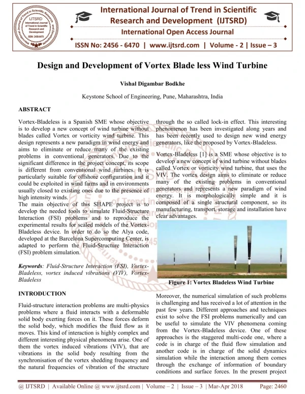
Control of Wind Turbine Flows using Vortex Generators Clara Velte Martin O. L. Hansen Dalibor Cavar Knud Erik Meyer MEK/Section of Fluid Mechanics DTU
Vortex generators (VGs) are commonly used on wind turbine blades and airplane wings From: [1] Wind Turbine Technology, Spera D.A (editor) ASME Press 1994. From: [2] Kermode A.C., Mechanics of flight, Pearson (11th edition) 2006.
Increase in aerodynamic efficiencythrough passive techniques Schematic figure of flow problem, 2D flow case. Suction side of airfoil is represented by bump in wind tunnel. Pressure distribution unsteady, 3D separation bubble. Separation might be controlled by vortex generators (VG:s). VGs transfer momentum from the free stream flow into the BL and thereby delay separation.
Schematic explanation of how a VG works: By creating a longitudinal vortex, high momentum air is transferred down into the bottom of the BL to increase momentum and thus resistance to adverse pressure gradients with the result of delaying stall.
Example of the potential of applying VGs on WT blades: ELKRAFT 1000 kW Turbine at Avedøre LM blade using NACA airfoils for outer part and thick FFA airfoils for the inner part ~ 25 % power increase @ 15 m/s From: [3] S. Øye, The effect of Vortex Generators on the performance of the ELKRAFT 1000 kW Turbine, 9th IEA Symp. On Aerodynamics of Wind Turbines, 1995.
To optimize the use of VGs, DSF has funded a project to study • the detailed flow behind the devices and thus better understand the physics. A fundamental study. • SPIV and LDA measurements in low speed wind tunnel at DTU • - to create a benchmark • Simulations using CFD (LES & DES)
[5] Godard G., Stanislas M., Control of a decelerated boundary layer. Part 1: Optimization of passive vortex generators, Aerospace Science and Technology Progress in Aerospace Sciences 10 (2006) 181-191 Optimization and characterization study of VGs. A bump is designed to keep the flow on the verge of separation. The wall shear stress is measured with a hot film
It is concluded that an optimum geometry is: Counter rotating triangular VGs h/ =0.37, L/h= 2.5, l/h=2, /h=6, =18o Reproduced from [5]
SPIV was used for characterization of the flow Baseline VGs The grey scale indicates the out-of-plane velocity component and the arrows the in-plane velocities. x/h=22 x/h=38 x/h=57 Reproduced from [5]
Non-dimensional streamwise velocity from HW measurements at point of minimum skin friction in plane of symmetry (Reproduced from [5])
- The flowfield (velocity, turbulence) will be measured and described very thoroughly (SPIV & LDA). - CFD computations will be performed and compared with measurements (LES & DES).
Status: The wind tunnel is under severe reconstruction. The main reason is for obtaining better optical access. Methods are being tested to decrease effects from reflections. LES computations of the clean bump have been initiated.
Some sample results, stereoscopic PIV x/h=4 The colour indicates the out-of-plane velocity component and the arrows the in-plane velocities. x/h=6 x/h=10
Rhodamine 6G Absorbs light at ~ 530 nm Emits light at ~ 560 nm Camera equipped with green pass filter (~532 nm) Low sensitivity to temperature & pH-value
Reflections from bump surface Black paint Black paint + R6G x/h=0 x/h=1 x/h=2 x/h=4 x/h=6
Reflections from bump surface & VGs Black paint Black paint + R6G x/h=0 x/h=1 x/h=2