Download
1 / 61
1.12k likes | 2.08k Views
Chapter 3 ELECTRICAL PROPERTIES OF MATERIAL. INTRODUCTION. CO1: Ability to describe , compare and analyze problems related to engineering materials including mechanical, electrical and magnetic properties. Contents. Energy band Types of electrical conduction

E N D
INTRODUCTION CO1: • Ability to describe, compare and analyze problems related to engineering materials including mechanical, electrical and magnetic properties.
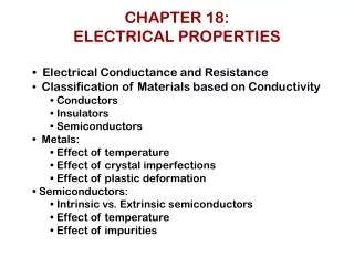
Contents • Energy band • Types of electrical conduction • Electrical properties in metals # Electron mobility in metal # Electrical resistivity in metal • Electrical properties of intrinsic semiconductors • Electrical properties in insulators • Dielectric behaviors and polarization
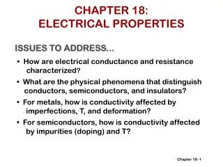
(3.1) ENERGY-BAND MODEL FOR ELECTRICAL CONDUCTION • The magnitude of the electrical conductivity is strongly dependent on the number of electrons available. • The number of electrons available for electrical conduction in a particular material is related to the arrangement of electron levels. • However, not all electrons will accelerate in the presence of an electric field.
Energy Bands • Energy gap-the difference between the energy levels of any two orbital shells • Band-another name for an orbital shell (valence shell=valence band) • Conduction band –the band outside the valence shell where it has free electrons.
Energy band-model for Insulator • Consists of a lower filled valence band and an upper empty conduction band. • These bands are separated by a relatively large energy gap (Eg). • Electrons in valence band are tightly bound to their bonding atoms by ionic or covalent bonding. • Electrons need as much as 6 to 7 eV to be energized to ‘jump’ the gap enter into conduction band.
(3.2) TYPES OF ELECTRICAL CONDUCTION • Within most solid materials a current arises from the flow of electrons : Electronic Conduction • For ionic materials a net motion of charged ions is possible that produces a current : Ionic Conduction + + + + + + + + +
(3.3). ELECTRICAL CONDUCTION in METAL • Ohm’s Law: V = IR • Electrical Resistance: (Unit is Ω) • Electrical Conductivity: (Unit is S/m) • Electrical resistivity, ρ (unit is Ωm) is a constant for a material at a particular temperature.
Electrical conductivities of some metals and alloys at room temperature Metals have high conductivities because of the large numbers of free electrons that have been excited into empty states above the Fermi energy. Thus, n has a large value in the conductivity expression
Conductivity: Comparison CERAMICS Soda-lime glass 10 -9 Concrete 10 -13 Aluminum oxide <10 SEMICONDUCTORS POLYMERS -14 -4 Polystyrene <10 Silicon 4 x 10 -10 -15 -11 -17 0 Polyethylene 10 -10 -10 Germanium 2 x 10 -6 GaAs 10 insulators semiconductors -1 -1 • Room T values (Ohm-m) = ( - m) METALS conductors 7 Silver 6.8 x 10 7 Copper 6.0 x 10 7 Iron 1.0 x 10 Ceramics According to the comparison, Which one is the best material in conductivity and the poor material in conductivity?
Example 1: Conductivity Problem A copper wire with length of 100 m carry a 2.5 A of current with potential difference of 1.5 V. Determine minimum diameter of the wire and its resistance. Given electrical conductivity, σ of copper is 6.0 x 10⁷ (Ω m)-1 100m - e I = 2.5A + - Cu wire DV
TRY IT YOURSELF! A 0.9 V potential difference is maintained across a 1.5 m length of tungsten wire that has a cross-sectional area of 0.6 mm2. What is the current in the wire? Given resistivity of tungsten is 5.6 x 10⁻⁸Ωm.
TRY IT YOURSELF! A resistor is constructed of a carbon rod that has a uniform cross-sectional area of 5.00 mm2. When a potential difference of 15.0 V is applied across the ends of the rod, there is a current of 4.00 x 10⁻³ A in the rod. Given resistivity of carbon is 3.5 x 10⁻⁵Ωm. Compute: a). The resistance of the rod. b). The rod’s length.
TRY IT YOURSELF! A cylindrical aluminium specimen having entire 57 mm length and 7.0-mm diameter. (a) Compute the electrical conductivity of which a current of 0.25A passes in an axial direction and voltage of 24 V is measured across two probes that are separated by 45 mm. (b) Compute the resistance over the entire 57 mm of the specimen.
ELECTRON MOBILITY in a CONDUCTING METAL Drift Velocity µe – Electron Mobility (m2/V s) • The average electron velocity in the direction of the force imposed by the applied field. • It is directly proportional to the electric field Conductivity n = number of free electron per m3 IeI = absolute magnitude of charge electron (1.6 x 10⁻¹⁹ C)
Charged particles do not travel in a straight line through a conductor, because they collide with other particles in the material. We therefore use the average speed the particle travels at along the conductor. This is called the drift velocity. Charged particles do not travel in a straight line through a conductor, because they collide with other particles in the material. We therefore use the average speed the particle travels at along the conductor. This is called the drift velocity. Charged particles do not travel in a straight line through a conductor, because they collide with other particles in the material. We therefore use the average speed the particle travels at along the conductor. This is called the drift velocity. http://www.s-cool.co.uk/a-level/physics/current-charge-and-voltage/revise-it/drift-velocity
ELECTRON MOBILITY • A force is brought to bear on the free electrons; When an electric field is applied and they all experience an acceleration in a direction opposite to that of the field, by virtue of their negative charge. • Current increasing with time and reaches a constant value indicating that there exist “frictional force”. • “Frictional force” result from the scattering of electron by imperfections in the crystal lattice: impurity atom, vacancies, interstitial atoms, dislocations, thermal vibration of atom itself. • The scattering phenomenon is manifested as a resistance to the passage of an electric current. • Each scattering event causes an electron to lose kinetic energy and to change its direction of motion. Path of an electron that is deflected by scattering events.
Frenkel defect, Frenkel pair, or Frenkel disorder is a type of point defect in a crystal lattice. The defect forms when an atom or cation leaves its place in the lattice, creating a vacancy, and becomes an interstitial by lodging in a nearby location not usually occupied by an atom. • Schottky defect is a type of point defect in a crystal lattice. The defect forms when oppositely charged ions leave their lattice sites, creating vacancies.
EXERCISE 1 (a) Calculate the drift velocity of electrons in copper at room temperature and when the magnitude of the electric field is 500 V/m and electron mobility for copper is 0.0030 m2/V-s. (b) Under these circumstances, how long does it take an electron to traverse a 25-mm length of copper wire?
ELECTRICAL RESISTIVITY OF METALS Total resistivity (ρtotal) of a metal is the sum of the contributions from thermal vibrations, impurities and plastic deformation ρt = thermal resistivity ρi = impurity resistivity ρd = deformation resistivity
Influence of Temperature ρ0C = electrical resistivity at O0C αt = coefficient temperature of resistivity. T = temperature of metal For all pure metal and all the copper-nickel alloy, the resistivity rises linearly with temperature above about -200 C. Thermal, impurity, and deformation contributions to the resistivity are indicated at -100ºC Temperature increase, ion cores vibrate more and a large number of phonons scatter conduction electrons. Hence, mean free paths and relaxation times between collisions decreases.
Influence of Impurities ci - Impurity concentration A - Composition-independent constant • Zinc element added to pure copper metal. • Impurity (zinc) cause additional scattering of the conduction electrons. • Thus increase the electrical resistivity and decrease the electrical conductivity. Room-temperature electrical resistivity versus composition for copper–zinc alloys.
Influence of Deformation • Structural imperfections increase the resistivity. • Type of imperfections: -- dislocations -- grain boundaries -- vacancies -- impurities atoms These act to scatter electrons so that they take a less direct path.
180 50 r 160 Ohm-m) 40 140 125 30 30 120 Resistivity, Yield strength (MPa) -8 20 100 (10 21 wt%Ni 10 80 0 60 0 10 20 30 40 50 0 10 20 30 40 50 wt. %Ni, (Concentration C) wt. %Ni, (Concentration C) From step 1: CNi = 21 wt%Ni QUESTION: ESTIMATING CONDUCTIVITY Estimate the electrical conductivity of a Cu-Ni alloy that has a yield strength of 125 MPa.
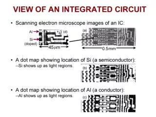
(3.4). ELECTRICAL PROPERTIES of INTRINSIC SEMICONDUCTORS • Semiconductors: Conductors between good conductors and insulators. • Intrinsic Semiconductors: Pure semiconductors • Conductivity depends on its inherent properties. • Example: Silicon (Si) , Germanium (Ge) – each atom contributes 4 valence electrons for covalent bond. • Valence electrons are excited away from their bonding position when a sufficient energy is supplied. • Moved electron leaves a hole behind and become free conduction electrons.
Electrical Conduction in Intrinsic semiconductor • In intrinsic semiconductors, electrons and holes are created in pairs. • Both electrons and holes are charge carriers • Electrical conductivity of a semiconductor : n = number of intrinsic carriers per m3. lel = absolute value of electron/hole charge (1.60 x 10⁻¹⁹ C). μe = mobility of electrons. μh = mobility of holes.
Effect of Temperature on Intrinsic Semiconductors • The conduction band is completely empty at 0K. • At higher temperatures, valence electrons are excited to conduction bands. • Conductivities increase with increasing temperature. Eg = energy gap. K = boatman's constant. T = temperature, K. σ0 = constant depending on the mobility.
(3.5). ELECTRICAL PROPERTIES of EXTRINSIC SEMICONDUCTORS • Extrinsic semiconductors have impurity atoms (100-1000 ppm) that have different valance characteristics. • n–type extrinsic semiconductors: Impurities donate electrons for conduction. • Example:- Group V A atoms ( P, As, Sb) added to silicon or Ge.
p–type extrinsic semiconductors: Group III A atoms when added to silicon, a hole is created since one of the bonding electrons is missing. • When electric field is applied, electrons from the neighboring bond move to the hole. • Boron atom gets ionized and hole moves towards negative terminal. • B, Al, provide acceptor level energy and are hence called acceptor atoms. • Doping: Impurity atoms (dopants) are deposited into silicon by diffusion at 11000C.
Effect of Temperature on Extrinsic Semiconductors • Extrinsic range: Electrical conductivity increases with temperature as more and more impurity atoms are ionized. • Exhaustion range (for n-type): temperature at which donor atom becomes completely ionized . • Saturation range (for p-type): Acceptor atoms become completely ionized.
Further increase in temperature results in intrinsic conduction becoming dominant. • Intrinsic range: The higher temperature provide sufficient activation energies for electron to jump the semiconductor gap (1.1 eV for silicon).
DIELECTRIC BEHAVIOR • A dielectric material is one that is electrically insulating (nonmetallic) and exhibits or may be made to exhibit an electric dipole structure. • There is a separation of positive and negative electrically charged entities on a molecular or atomic level. • Dielectric materials are utilized in capacitor to store the electrical energy. Dipole interaction with electric field: ϵ - permittivity ϵr Dielectric Constant
Capacitors and Capacitance: Capacitor physics and circuit operation • https://www.youtube.com/watch?v=f_MZNsEqyQw
DIELECTRIC BEHAVIOR Polarization (P): The orientation of a dipole along the applied electrical field. • It causes charge density to increase over that of a vacuum due to the presence of the dielectric material so that . E is the electrical field. D is the surface charge density of a capacitor, also called dielectric displacement.
POLARIZATION • The charge stored on capacitor plates for a vacuum • (b) The dipole arrangement in an unpolarized dielectric • (c) the increased charge storing capacity resulting from the polarization of a dielectric • material.
POLARIZATION D - Dielectric Displacement Vacuum condition : Non-Vacuum condition : Dielectric displacement with present of dielectric material : P - Polarization Polarization of a dielectric medium :
POLARIZATION Process of dipole alignment • Imposed forces (and torque) acting on a dipole by an electric field • (b) Final dipole alignment with the field
DIELECTRIC CONSTANTS AND STRENGTHS FOR SOME DIELECTRIC MATERIALS
TYPES OF POLARIZATION • Electronic Polarization • It results from a displacement of the center of the negatively charged electron cloud relative to the positive nucleus of an atom by the electric field. • This polarization type is found in all dielectric materials and, of course, exists only while an electric field is present. Electronic polarization that results from the distortion of an atomic electron cloud by an electric field
Types Of Polarization • Ionic Polarization • Ionic polarization occurs only in materials that are ionic. • An applied field acts to displace cations in one direction and anions in the opposite direction, which gives rise to a net dipole moment. • The magnitude of the dipole moment for each ion pair (pi) is equal to the product of the relative displacement (di) and the charge on each ion, or Ionic polarization that results from the relative displacements of electrically charged ions in response to an electric field
Types Of Polarization • Orientation Polarization • Orientation polarization is found only in substances that possess permanent dipole moments. • Polarization results from a rotation of the permanent moments into the direction of the applied field. • This alignment tendency is counteracted by the thermal vibrations of the atoms, such that polarization decreases with increasing temperature. Response of permanent electric dipoles (arrows) to an applied electric field, producing orientation polarization.
FREQUENCY DEPENDENCE OFTHE DIELECTRIC CONSTANT • In many practical situations the current is alternating (ac); that is, an applied voltage or electric field changes direction with time. Dipole orientations for (a) one polarity of an alternating electric field and (b) for the reversed polarity.
FREQUENCY DEPENDENCE OF THE DIELECTRIC CONSTANT • The dielectric constant (sometimes called the ‘relative permittivity’) is the ratio of the permittivity of the dielectric to the permittivity of a vacuum. • Dielectric constant of a material expresses the ability of a material to polarise in response to an applied field. • The greater the polarisation developed by a material in an applied field of given strength, the greater the dielectric constant will be. • the greater the dielectric constant, the material tends to reduce any field set up in it.
FREQUENCY DEPENDENCE OF THE DIELECTRIC CONSTANT • A dielectric becomes polarised in an electric field. The direction of the polarisation will also switch in order to align with the new field. • This cannot occur instantaneously: some time is needed for the movement of charges or rotation of dipoles. • If the electrical field is switched, there is a characteristic time that the orientational polarisation (or average dipole orientation) takes to adjust, called the relaxation time. • Typical relaxation times are ~10-11 s. Therefore, if the electric field switches direction at a frequency higher than ~1011 Hz, the dipole orientation cannot ‘keep up’ with the alternating field, the polarisation direction is unable to remain aligned with the field, and this polarisation mechanism ceases to contribute to the polarisation of the dielectric.
FREQUENCY DEPENDENCE OF THE DIELECTRIC CONSTANT • As frequency increases, the material’s net polarisation drops as each polarisation mechanism ceases to contribute, and hence its dielectric constant drops. • With each direction reversal, the dipoles attempt to reorient with the field, in a process requiring some finite time. • For each polarization type, some minimum reorientation time exists, which depends on the ease with which the particular dipoles are capable of realignment. • A relaxation frequency is taken as the reciprocal of this minimum reorientation time.