Download
1 / 63
640 likes | 670 Views
6.1. STRUCTURAL ANALYSIS. The photo-interpretation of the planar structures like bed, foliation, joint and fault is termed as structural analysis. 6.1.1. Bedding ATTITUDE: The position of a bed in relation with the horizontal. DIP & STRIKE: Determines the position of a tilted bed .

E N D
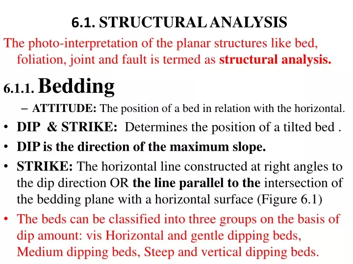
6.1. STRUCTURAL ANALYSIS The photo-interpretation of the planar structures like bed, foliation, joint and fault is termed as structural analysis. 6.1.1. Bedding • ATTITUDE: The position of a bed in relation with the horizontal. • DIP & STRIKE: Determines the position of a tilted bed . • DIP is the direction of the maximum slope. • STRIKE: The horizontal line constructed at right angles to the dip direction OR the line parallel to the intersection of the bedding plane with a horizontal surface (Figure 6.1) • The beds can be classified into three groups on the basis of dip amount: vis Horizontal and gentle dipping beds, Medium dipping beds, Steep and vertical dipping beds.
Figure 6.1. Relation between strike-dip-bedding plane and talus. The talus tends to reduce the angle of sloping. E-E is the edge or rim of a hard bed, usually marked on aerial photographs.
6.1.1.1. Horizontal and gentle dipping beds. • Beds having one to five degree dip amount are named as horizontal beds. E.g in alluvial deposits, terraces, talus and undisturbed deposits. • A landscape of this type is that of a CANYON-MESA type (Figure 6.2). • The hills when isolated have the form of a flat table mountain or MESA. • The valleys are deep dissected cut-in CANYONS. • The slope of a mesa or sides of a canyon are step-like. • The hard beds, like sandstone or limestone, form near perpendicular cliffs, the softer shales form slopes.
Figure 6.2. • Hard beds form a mesa when horizontal, • A dipslope or cuesta when tilted, • A hogback when in steep attitude. • Ss is a subsequent or strike controlled stream; Sf a fault controlled stream; Rs a resequent stream, and Ob an obsequent stream.
The conspicuous photographic characteristics of horizontal beds are as follows: • 1. The flat lying or nearly horizontal beds are easily distinguished by tonal contrast and different resistance to erosion. The tonal contrast is expressed as bands following or extending parallel to the topographic contours. They are also loop-like shaped on the aerial photographs (Figure 6.3). • 2. In the case of alternating resistant and non-resistant beds slope characteristics (breaks in slope) help in recognizing each unit. • 3. The drainage pattern on flat lying beds is generally dendritic unless they are controlled by joint or fault. • 4. A dip of half a degree can be observed on aerial photographs unless beds are obscured or obliterated by talus or scree. • 5. The land shape of canyon-mesa type topography is underlain by horizontal or flat-lying sediments.
Figure 6.3. Dendritic drainage patterns characteristically develop on horizontal strata and cut canyons or valleys in which progressively older rock units are exposed. As a result, the map patterns of horizontal strata parallel stream valleys and produce a dendritic pattern on the geologic map. The contacts of rock units of horizontal strata will parallel the contours. Escarpments and gentle slopes generally develop on resistant and nonresistant beds respectively and thus produce variations in the width of the map outcrop patterns.
On steep cliffs the upper and lower contacts (as seen on the map) will be close together, whereas on a gentle slope of the same formatian the contacts will appear further apart. • Gently dipping strata will develop the same basic outcrop pattern as horizontal beds. • The contacts between rock units in gently dipping strata, when traced far enough up a valIey, however, will be seen to cross topographic contours and form a large V-shaped pattern which points in the direction in which beds dip.
6.1.1.2. Medium dipping beds • The beds with dips ranging from 5-35 degrees • Landforms of this nature constitute DIPSLOPE or CUESTA (Figure 6.2) • The dipslope or questa is an asymmetric ridge; one slope is gentle, long and agree with the dip direction of the bed. Other slope is short and steep. • The longer is called the face slope, which is parallel with the dip of the hard bed, and the other is the scarp or steep slope, which inclines away from the face slope. • Because the dipslope of a gentle or medium dip is attacked by erosion from two opposite quarters, the resulting watershed will shift. On the steeper slope the streams will erode with greater intensity, than on the side with a gentle slope. The divide will therefore shift gradually from the steeper slope towards the gentle or face slope until an equilibrium is reached (Figure 6.4).
Figure 6.2. • Hard beds form a mesa when horizontal, • A dipslope or cuesta when tilted, • A hogback when in steep attitude. • Ss is a subsequent or strike controlled stream; Sf a fault controlled stream; Rs a resequent stream, and Ob an obsequent stream.
Figure 6.4. Recession of an escarpment. Escarpment (E) started at the initial position IPS where a strike controlled stream began to erode shale Sh2 which is overlying Ss1. R and arrow indicated direction of receding watershed. D is a dipslope of Ss2.
The main photo-characteristics of medium dipping beds are as follows: 1. The dip amount, dip direction and the strike can be determined well on these beds. 2. The outstanding land shape developing on the medium dipping beds is the DIPSLOPE or QUESTA. 3. Where bedding is expressed by bands of differing photographic tone or by topographic breaks in slope due to the resistance of beds, the rule of V's may be applied to determine the direction of dip; that is, where the trace of a bed intersects a stream valley a V in the outcrop pattern will point the direction of dip (Figure 6.5, 6.6). But if the direction of dip and direction of stream flow are the same and the stream has a gradient greater than the amount of dip, the case will be reverse.
6.1.1.3. Steep and vertical beds • The beds having dips more than 35 degrees • are considered to be steeply dipping beds. • In practice, steep or vertically dipping beds • are seldom indicative to which side of the • ridge the bed is dipping. • Dips over 65 degrees seem vertical on • photographs because of stereoscopic • exaggeration.
Figure 6.6. When a sequence of rocks is ti1ted and truncated by erosion, the outcrop patterns will appear as bands which, on a regional basis, are roughly parallel. Important variations in details of the basic pattern are developed in areas dissected by erosion and should be carefully analyzed, for they provide important information concerning the subsurface structure. When dipping strata are traced across a valIey, a V-shaped outcrop pattern is produced which points in the direction of dip. Exception to the rule is possible if the degree of bedding dip is less than the gradient of the valIey, but such conditions are seldom encountered.
The size of the outcrop pattern V is inversely proportion al to the magnitude of dip: • 1. low angle dip -large V (front part of Figure) • 2. high angle dip - small V • 3. vertical dip - V is absent (back part of Figure) • Careful examination of Figure will reveal several additional relationships • basic to geologic maps: • Older beds dip toward younger beds unless the sequence is overturned. • Outcrop width depends on a. thickness of the beds • b. dip of the beds (low dip maximum width) • c. slope of the topography (steep slope minimum width)
The main photo-characteristics of the steep and vertical dipping beds are as follows: 1. The diagnostic landshape developing on these beds is HOGBACK (Figure 6.2). Hogbacks are sharp, straight or slightly curved ridges with the two opposing slopes dipping at same angles. 2. Vertical beds are strongly eroded, worn, and often covered by talus on both sides of a hogback ridges. 3. The long axis of the hogback is parallel to the strike of the bedding. By using the long axis, one can easily determine strike direction. 4. Using the scale of the aerial photograph, the true thickness of vertical or nearly vertical bed can be measured directly without the aid of any formula.
Determination of the direction of dip of inclined beds from aerial photographs 1. Dip direction is readily apparent where topographic surfaces coincide with bedding surfaces (Figure 6.7).
2. Dip direction can be determined using the rule of V (Figure 6.6, 6.9). The apex of V always points the dip direction. The long and narrow V shape shows less dip amount or gently dipping beds while short and wide V shape refers medium and steep dipping beds. 3. The drainage characteristics may also be used to find the dip direction in the areas, particularly those of low relief, where beds are obscured by surfical materials or vegetation. Where the dips are gentle the relatively long tributary systems commonly flow down the face slopes, whereas short tributary systems will characterized back slopes (Figure 6.8). When the dip is steep, in other words, it is over the 45 degrees, the rule is reverse (Figure 6.10).
Figure 6.9. Relationship between outcrop pattern and type of the bed
4. Slope asymmetry may be used to find the dip direction. The gentle slope of a questa or dip slope indicates dip direction (Figure 6.10). 5. In heavily vegetated areas the tree crowns fall in the direction of slope. Figure 6.10
To interpret the lineaments resulting from the dipping beds, the following characteristics should be observed on aerial photographs: a. They have to be persistent ridges when the bed is more resistant to the erosion than the adjacent bed or rock unit. b. They have to be approximately parallel to one another. If there is an abrupt ending of this parallelism, it indicates a structural features like a fault. c. Ridges of hard beds tend to be found in groups rather than single.
6.1.2. Folded structures • Layers of rock are laid down originally in a horizontal position, with younger one on top. • Sequences are compressed by the tangential pressure, they are tilted, warped, folded and fractured resulting the orogenic belts or terrain. • The difference in rigidity of layers, changing direction or intensity of pressure, causes fracturing of the strata. • Rigid, hard beds, like ss or ls, will break up into blocks when exposed to folding movements near the surface. • Beds of greater softness or plasticity like shale or clay when compressed in depth, act just like viscous fluids. Folding and fracturing are processes linked closely to each other.
In separating lithologic units on aerial photographs, the question arises continually which is older, which the younger? • On areas with a low relief, dipslopes are often too indistinctive to obtain evidence of the sequence of certain strata. • Older beds are exposed in fold cores while the younger ones occur in the flanks and troughs. • Tectonic landforms and structural features depend on the intensity of tangential pressure. E.g slight pressure will result in gentle warping or open folds, while high presure, steep and overturned folds (Figure 6.11).
Figure 6.11. Types of folds. The type depends on the intensity of tectonic pressure. An is an anticline, with crest C and anticlinal axis, AAx. The two slopes are called limbs or flanks (L). The syncline (Sy) and its axis (SAx) indicate that the structure is symmetric. When the axial plane (O-FAx) is tilted, an assymetric or overfold, will result (OF). Continuous tectonic pressure will result in a recumbent or overturned fold (RF). This fold is usually connected with an overthrust (O-T) fault. Recumbent folds may become covers or nappes in intensively folded mountainous areas.
On the basis of dip amount of flanks or limbs, folds are classified into three groups, namely gentle folds, medium folds and steep folds. a. Gentle folds. The dip amount of the limbs range from 2 to about 10 degrees. Folds in this range have long gentle dipslopes. Gentle folding is of great importance to the petroleum geologist because such structures are favorable for accumulation of oil. b. Medium folds. The dip amount of the limbs range from 10 to 35 degrees. The landforms are medium grade dipslopes. Such folded belts follow orogenesis. c. Steep folds have dips from 35 to vertical. When eroded and in the steeper range, it is often not possible to construct the approximate axial part of these folds.
There are several types and forms of folds namely, anticline and syncline. a. Anticline. Anticlines are positive folds with bedding planes dipping away from a line called the axis of the structure (Figure 6.11). The dip amount increases towards the flanks and low or horizontal on or near the axis. The axis which runs with the highest part of the fold is a theoretical plane of vertical or tilted attitude cutting the anticlinal fold at its highest part. It is, therefore, marked with a line or symbol on maps. Axes do not continue horizontally along an anticlinal fold. They plunge according to the dip of the bedding planes, and are named as plunging anticline (Figure 6.12). Anticlines are of essential importance for petroleum prospecting.
Every anticline, short or long, has a part where the beds are highest, or where, the oldest beds appear at the surface of a near level terrain. From such an area, the beds are dipping radially in all directions, and the axis shows two plunges at opposite areas away from this highest part. These types of features are called as dome due to their dome like shape (Figure 6.13). Such structural features are of great economic importance in the respect of petroleum accumulation. b. Syncline. This structure is a negative fold. The beds on a syncline dip toward the central line, the synclinal axis, which runs along the deepest part of a tectonic trough. Synclines are of many types, similar to anticline. If the axis of syncline shows two plunges at opposite areas, these features are named as basin (Figure 6.14). Synclines have usually no economic interest for the oil geologist. For the hydrologist however, synclines are important because artesian wells can be successfully drilled in synclines.
Figure 6.12. The inclination of the axis is referred to as plunge and is of importance in analyzing the three-dimensional aspect of the fold. Plunging folds which have been truncated by erosion form a characteristic zig-zag outcrop pattern. A plunging anticline forms a V –shaped outcrop pattern with the apex (or nose) pointing in the direction of the plunge. Plunging synclines form a similar pattern, but the limbs of the fold open in the direction of plunge.
Figure 6.13. Eroded, dome-shaped structures form a roughly circular to elliptical outcrop with beds dipping away from a central area. Drainage patterns are helpful in interpreting domal structures because (1) they tend to form a radial pattern as streams develop on the less resistant beds and (2) streams cutting across the resistant beds permit one to apply the rule of V's to interpret the direction of dip. If the relative ages of rock units are shown on the map, a dome is readily recognized by older rocks located in the center of the structure.
Figure 6.14. A structural basin, when eroded and ex- posed at the surface, displays an elliptical or circular outcrop pattern similar to that of an eroded dome. The general outcrop pattern of both structures is similar, but two major features enable us to distinguish readily a basin from a dome: (1) Younger rocks crop out in the center of a basin, whereas older rocks are exposed in the center of a dome. (2) If the structure has been dissected by stream erosion, the V in the outcrop points toward the center of a basin and away from the center of a dome. In addition, the cliff or scarp formed on the resistant rocks of a basin faces outward, and the dip slope is inclined toward the center of the structure. This is exactly the opposite of the direction in which the slope is inclined in an eroded dome.
6.1.3. Structural landforms • Every region of sedimentary rocks will be eroded during and after accomplished folding. • Weak rock will be removed and the hard beds will remain as ridges or dipslope belts. • The resulting landforms depend on the distributions of hard and weak strata. • Positive forms will be mountains or ridges; negative forms will be valleys, troughs, or basins.
Tectonic terrace (tectonic bench or homocline) • These are incomplete anticlinal structures. • They have two flanks dipping in the same direction similar to a river terraces (Figure 6.15)
Anticlinal mountain:The axial part can be built up by a resistant and hard formation. • Along an anticlinal axis, older beds crop out, which are mostly harder and more resistant than younger formations which are not too well consolidated. • The core part will, therefore, remain and anticlinal mountain will result (Figure 6.16). • Anticlinal valley. When nonresistant and weak beds are exposed along an anticline and the flanks are of resistant material, the core of the fold will be carved out by subsequent stream and an anticlinal valley will result (Figure 6.16).
Figure 6.16. Block diagram of an anticlinal mountain and a synclinal valIey. The anticline (A.Mt.) forms a ridge. A thick sandstone bed (Ss2) is overlain by a sandy shale sSh. Consequent drainage C of sandy shale character forms dipslopes (D) which however do not conform with Ss2 below. The ,watershed W, however, follows the axis of the structure. The synclinal valley (S. V.) is formed by sandstone Ss1. It forms a trough with dipslopes (D) and alluvial fill (A). The shale at the left shows a strike controlled strato subsequent river (sR). At the center, stream sR follows the scarp in a similar sense. The tributaries from the anticline are resequent streams; the steep short gullies from the scarp obsequents (O). CgI is a base coinglomerate; B is base rock.
Synclinal valley. It is a type of landform which is associated with troughs (Figure 6.17). • Synclinal mountain. It is less frequent and occur when the core of the syncline is of hard rock and the older beds along the flanks are weak and removed by erosion (Figure 6.17).
FIGURE 6.17. Block diagram of a synclinal mountain and anticlinal valIey. The beds: Ss, sandstone; Sh, sha1e;sSh, sandy shale; Lst, limestone; CgI, conglomerate; and B, basement rock. At D is a sinkhole-studded gently dipping limestone surface, with internal drainage. It forms dip- slopes (D-D). Since the anticlinal crest (AV) falls into a sandy shale, a valley is eroded by a strike controlled stream. The syncline (SM) is formed by several hard beds. It is a mesa-type fiat trough. Talus cones (Tc) flattening the slope between sandstones 1 and 2, should not be confused with dipslopes. Note that shale at SM ex- presses the dip of beds. At sSh the shale is unconclusive to real dip of the complex.
6.1.4. Fractures Tectonic forces do not always cause the development of folds. Instead, the rocks may break or fracture. Faults and joints are examples of these types of deformational features. 6.1.4.1. Faults Faults are the deformational features of the Earth's crust along which a measurable movement takes place (6.18). On aerial photographs fault indications have one common property: they are always straight, or slightly curved. Straightness is inherent to all breaking phenomena of the crust. This stands mainly for resistant rocks, because, weak, plastic beds are bent rather than broken. The relative straightness of a fault indication is based on the straightness of the fault plane. This plane is always somewhat irregular or slightly curved. Normal faulting displays, as a rule, straightness along a certain length (Figures 6.18, 6.19). Curved fault traces are found only in reverse or overthrust fault.
Figure 6.18. Fault patterns on geologic maps are distinctive; they appear as lines or zones of displacement that abruptly offset structures and terminate contacts between formations. Thrust faults generally dip at a low angle. Because of the low-angle dip, the pattern of the fault trace is characteristically irregular and similar in many respects to the trace produced by low-dipping angular unconformities. In Figure 6.18, thrust faults are located at the base of the formations colored purple and blue. The trace of a thrust fault commonly forms a V across valleys, with the V pointing in the direction in which the fault dips. Normal and reverse faults usually dip at a high angle, so their outcrop patterns are relatively straight. Since older rocks are generally exposed on the upthrown block, the relative movement on most high-angle faults can be determined from the map relations alone.
Thick, resistant sandstone formations in the Colorado Plateau commonly show the characteristics of fracture systems in remarkable detail. The sandstone formation in this area is nearly horizontal. Normal faults are shown where the surface is placed vertically. Joint systems are accentuated by weathering and are expressed as cracks.
In a strike-slip fault, the displacement is parallel to the strike of the fault plane. Displacement on strike-slip faults may reach several hundred miles, so rock types of very different structure and geologic characteristics may be placed side by side after prolonged periods of movement. The trend of strike-slip faults is typically straight, in contrast to the irregular trace of thrust faults and the zigzag trace of normal faults. Small slivers or slices of foreign rock bodies may be caught in the strike-slip fault zone and are commonly expressed either as elongate troughs or ridges.
The lateral displacement of the crust in strike-slip faults does not produce high scarps. The fault line is, however, commonly arked by structural and topographic discontinuities, linear ridges and rivers, and offset drainage patterns. The offset drainage is usually very signifıcant, because it indicates the direction of displacement.