Download
1 / 41
410 likes | 512 Views
US Module Cluster. Report on Hybrid/Module Assembly, Metrology, and Testing/QA Abe Seiden UC Santa Cruz Dec 2001 SCT Week. Outline. Introduction Status of Infrastructure Results on Hybrids Results on Mechanics and Metrology Results on Electrical Modules Plan and Schedule. Introduction.

E N D
US Module Cluster Report on Hybrid/Module Assembly, Metrology, and Testing/QA Abe Seiden UC Santa Cruz Dec 2001 SCT Week
Outline • Introduction • Status of Infrastructure • Results on Hybrids • Results on Mechanics and Metrology • Results on Electrical Modules • Plan and Schedule
Introduction • US Cluster is to assemble and test 670 barrel modules and associated hybrids • LBL task: assembly, bonding, testing • UCSC task: bonding and testing • US Cluster works closely with RAL group in mechanical area. Common fixturing and procedures. Weekly scheduled phone conference.
Infrastructure • IV scan • Probe station in place and functioning • Interfaced to LabView and SCT database • Wafer Alignment • System up and running with Manchester code • Wafers placed and verified
Infrastructure -continued • Fixtures and Process • Year 2000 series RAL fixtures in use • New baseboard support plate upgrade in hand • 5 fixture sets to be ordered to enable 3 modules/day in production • Finisar glue robot programmed and in use • Glue mixing centrifuge on order
Infrastructure -continued • Fixtures and Process - continued • Locally designed custom fixtures: • Multi-Purpose Plate (MPP) for combined hybrid assembly, gluing, bonding, rework, and test. Various parts in hand or in shops. • Module Pickup Tool prototype in hand, RAL to adopt. • Hybrid Folding Fixture (HFF) prototype in use, new production design in process/shops. Used for bonding as well. • Storage cabinet system with gas flow in process.
Photos of MPP and associated fixtures Glue pattern template Die attach fixture Electronics holder
Infrastructure - continued • Bonding • K&S 1470 auto-bonder in regular use, 2nd unit on order. • Pull studies on K4 and mechanical sample are acceptable. • Prototype bonding fixtures now in use to be replaced by MPP and HFF. • Technicians trained • 2 full electrical modules bonded since 10/01.
Results on Hybrids • 3 K4 electrical hybrids have been assembled • 2 used in electrical modules (described later) • 1 used in irradiation program to study Idd problem • Conductive epoxy applied uniformly with template • Bonding to hybrid acceptable. • Concern with fanout surface quality and etching uniformity • Stock of K4 – 1 remains • Dummy hybrids built on Al bridges and used for bonding and mechanical studies
Results on Hybrids - continued • Hybrid production fixtures in fabrication • One K4 has been extensively reworked (chips damaged in thermal tests) – functions with new chips replaced (now part of electrical module).
Results on Mechanics and Metrology • Mechanical work focuses on refining full assembly and measurement process. • Only dummy modules are being fabricated at present • Dummy Atlas98 detectors. • Dummy alumina baseboards with old style Al washers or epoxy hole fixation points. Results on Z await PG baseboards. • Present module under study used old RAL ball/cone fixation into assembly fixture. • Module in fabrication now with new baseboard support plate from RAL, pin only fixation.
Mechanics and Metrology- continued • Metrology utilizes SmartScope, RAL metrology plate, same analysis flow as RAL. • Present analysis using locally written spreadsheet • RAL Perl code installed and in commissioning • Few micron error observed correlating front to back of metrology fixture using precision pin-hole array
In-plane metrology on 2nd dummy module(Alumina baseboard) • Stereo angle off by ~1mr • a2-a4 off by ~.13 mr • Overall Y shift of ~50 mm • No correction to software yet applied for fixture built-in error - this can remove Y shift • Stereo angle: need to re-survey fixtures
Next steps in metrology • Check analysis with RAL code • Complete 3rd dummy module using new RAL baseboard support plate • Derive new correction factors for assembly fixtures • Re-survey fixtures • Commission out of plane analysis • Build dummy modules with PG baseboards
Results on Electrical Modules: LBNL Module-1,2 • Two Modules built and tested at LBNL using: • ABCD3T and ABCD3T-A • Atlas98 detector/baseboard set glued ~1year ago • >This mechanical assembly preceeds the present • auto wafer alignment system • K4 hybrids • Old QMW boxes • Setup: • Water cooler to reach 25o C • External power supplies (both LV and HV) • Standard SCT readout system
Summary of Electrical Results • Leakage currents before and after mechanical assembly are consistent. • For LBNL Module 1: • 2 ABCD chips used had significant number of bad channels. This was know from wafer probe. (36 on chip 0 and 33 on chip 3). • Corner of fanout on Link-0, Master was cracked -> group of 18 open channels. Crack was present on hybrid as received. • Beyond such known problems only 1 other channel was lost in bond. • Acceptable results on gain, noise, thresholds, occupancy -> plots
Summary of Electrical Results - continued • For LBNL Module-2: • ABCD chip quality was not a problem • Considerable bonding problems from chips to fanout due to oxidized Al surface. Finally had to be cleaned with light abrasion but this resulted in 26 open lines on the fanout. • Bad etching on the fanout: lines between pads were too wide. Some shorting of adjacent bond feet resulted in 46 bad channels. • Beyond these documented problems, gain, noise, threshold uniformity and levels seem acceptable. However… • Glitch observed in all S-curves on Link-1. Also appears as structure in occupancy plot. ?oscillation?
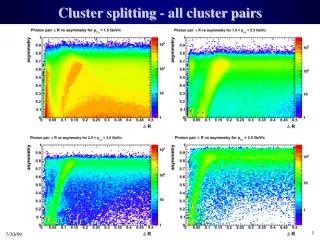
LBL-Module1 LBL-Module2 Measured Module Noise for each ASIC Measured noise (ENC) on each of the 12 ASICs of two modules made with ABCD3T or ABCD3T-A The temperature of the hybrid was about 25o C (measured at the thermistors) Bias detector voltage = 150 V
LBL-Module1 VT50-Gain-Offset-Input Noise – Link 0 VT50, Gain, Offset, and Input Noise for Link 0 from the Response vs Channel Test. The first 16 channels of Chip0 have very low noise due to a crack in the fan-out Bad channels on chips 0 (36) and 4 (33) were present on ABCD chips at wafer probe
LBL-Module1 VT50-Gain-Offset-Input Noise – Link 1 VT50, Gain, Offset, and Input Noise for Link 1 from the Response vs Channel Test. Chip4 has higher noise (see also plot “Measured Module Noise for each ASIC”)
LBL-Module1 Mean Noise Occupancy Mean noise occupancy of all channels of LBL-Module1, at 25o C The noise occupancy at 1fC threshold is 1.24x10⁻⁴
LBL-Module1 S-curves – Link 0 Curves of occupancy versus threshold superimposed for every channel of Link 0. Every fourth channel (32 total) of each ASIC appears in each plot. Chip0 and Chip3 have lots of bad channels.
LBL-Module1 S-curves – Link 1 Curves of occupancy versus threshold superimposed for every channel of Link 1 Every fourth channel (32 total) of each ASIC appears in each plot
LBL-Module1 TrimDAC Characteristics – Link 0 TrimDAC settings versus threshold for each ASIC of Link 0
LBL-Module1 TrimDAC Characteristics – Link 1 TrimDAC settings versus threshold for each ASIC of Link 1
LBL-Module1 TrimDAC Response TrimDAC response for TrimRange 0
LBL-Module2 VT50-Gain-Offset-Input Noise – Link 0 VT50, Gain, Offset, and Input Noise for Link 0 from the Response vs Channel Test. A few channels of Chip0 and Chip2 were short-circuited in the bonding process
LBL-Module2 VT50-Gain-Offset-Input Noise – Link 1 VT50, Gain, Offset, and Input Noise for Link 1 from the Response vs Channel Test. Open due to fanout seen on chip 7 low noise.
LBL-Module2 Mean Noise Occupancy Mean noise occupancy of all channels of LBL-Module2, at 25o C The noise occupancy at 1fC threshold is 6.5x10⁻⁵ . Note structure around 90 mV.
LBL-Module2 S-curves – Link 0 Curves of occupancy versus threshold superimposed for every channel of Link 0 Every fourth channel (32 total) of each ASIC appears in each plot
LBL-Module2 S-curves – Link 1 Curves of occupancy versus threshold superimposed for every channel of Link 1 Every fourth channel (32 total) of each ASIC appears in each plot. Note kink seen around 90%
LBL-Module2 TrimDAC Characteristics – Link 0 TrimDAC settings versus threshold for each ASIC of Link 0
LBL-Module2 TrimDAC Characteristics – Link 1 TrimDAC settings versus threshold for each ASIC of Link 1
LBL-Module2 TrimDAC Response TrimDAC response for TrimRange 0
Plan and Schedule • Qualification of metrology to continue through January • Dummy with PG baseboards – require components. • Site qualification series Jan-March 02. Don’t foresee problems with electrical assembly (assuming good fanout quality) based upon results shown for LBNL electrical modules. • Can start hybrid production fab with arrival of LBNL production fixtures and components. • Proposed start-up schedule based upon initial serial ramp-up to fully validate process. See upcoming slides. • Multiple fixtures sets to allow upto 3 modules/day only required after serial ramp-up is complete (~June 02).
Plan and Schedule -continued • Progress in commissioning and in production start-up depends critically on availability of components in the US • Hybrids: need more kaptons and chips! Parts for qualification module could be built now. • Dummy modules: need PG baseboards ( 2 old style in hand) - need more by January. • Site qualification modules: will need hybrids and chips, detectors (only have 6 remaining in-hand), and baseboards in January. • Ditto for module production.
Hybrid Production Plan • 08-Feb-02 start hybrid production 10 hybrid in 20d • 15-Mar-02 1.5% tested 1/day • 15-Apr-02 4.5% 2.6/day • 29-Jun-02 25% “ • 05-Dec-02 50% “ • 08-Aug-03 100% “
Module Production Plan • 16-Mar-02 start module production 10 module in 80d • 15-Jul-02 1.5% produced • 15-Aug-02 4.5% 20 module @1/day • 02-Sep-02 7.5% 20 module @2/day • 10-Nov-02 25% 2.8/day flat-top • 20-Feb-03 50% “ • 22-Aug-03 100% “