Download
1 / 70
740 likes | 954 Views
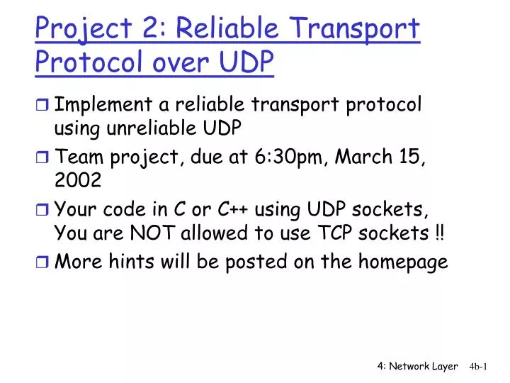
Project 2: Reliable Transport Protocol over UDP. Implement a reliable transport protocol using unreliable UDP Team project, due at 6:30pm, March 15, 2002 Your code in C or C++ using UDP sockets, You are NOT allowed to use TCP sockets !! More hints will be posted on the homepage.

E N D
Project 2: Reliable Transport Protocol over UDP • Implement a reliable transport protocol using unreliable UDP • Team project, due at 6:30pm, March 15, 2002 • Your code in C or C++ using UDP sockets, You are NOT allowed to use TCP sockets !! • More hints will be posted on the homepage 4: Network Layer
Reliable Data Transfer • Able to handle packet loss and corruptions • 16-bit sequence number (for simplicity, the sequence # is in packets) • CRC-16 for error checking (a sample code will be posted soon) • Select Repeat Protocol • Window size fixed at 16 packets; each packet is 512bytes including the header you designed • EOF flag indicates end of file • Not enough bits: padding • Retransmission timeout = 1second 4: Network Layer
Suggested Steps • #1: Read UDP sockets, and understand the examples • Remember now you use sendto() and recvfrom() • Specify your own server UDP port number • #2: Work out a simple server and a client for file transfer using UDP sockets • Adapt from the given examples • Check whether you transfer the whole file correctly. • Typically you will NOT experience packet loss 4: Network Layer
Suggested Steps • #3: Build a simple Stop and Wait protocol • Window size is 1 packet • #3.a Check for lost packet • Add sequence number • Add ACKNOWLEDGMENT packet • #3.b Add retransmission timeout to handle lost packet • How to handle timeout • #3.c Handle corrupted packet • Add CRC at the sender • Verify CRC at the receiver • #4: Select Repeat Protocol • #4.a: set sender’s window = 16 packets, but receiver window is still 1 packet (this is the Go-back-N protocol) • #4.b: set the receiver’s window =16 packets 4: Network Layer
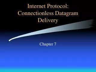
IP datagram format IP protocol version number 32 bits total datagram length (bytes) header length (bytes) type of service head. len ver length for fragmentation/ reassembly fragment offset “type” of data flgs 16-bit identifier max number remaining hops (decremented at each router) upper layer time to live Internet checksum 32 bit source IP address 32 bit destination IP address upper layer protocol to deliver payload to E.g. timestamp, record route taken, pecify list of routers to visit. Options (if any) data (variable length, typically a TCP or UDP segment) 4: Network Layer
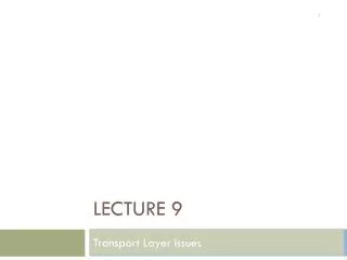
network links have MTU (max.transfer size) - largest possible link-level frame. different link types, different MTUs large IP datagram divided (“fragmented”) within net one datagram becomes several datagrams “reassembled” only at final destination IP header bits used to identify, order related fragments IP Fragmentation & Reassembly fragmentation: in: one large datagram out: 3 smaller datagrams reassembly 4: Network Layer
length =1500 length =1500 length =4000 length =1040 ID =x ID =x ID =x ID =x fragflag =0 fragflag =0 fragflag =1 fragflag =1 offset =0 offset =1480 offset =0 offset =2960 IP Fragmentation and Reassembly One large datagram becomes several smaller datagrams 4: Network Layer
used by hosts, routers, gateways to communication network-level information error reporting: unreachable host, network, port, protocol echo request/reply (used by ping) network-layer “above” IP: ICMP msgs carried in IP datagrams ICMP message: type, code plus first 8 bytes of IP datagram causing error ICMP: Internet Control Message Protocol TypeCodedescription 0 0 echo reply (ping) 3 0 dest. network unreachable 3 1 dest host unreachable 3 2 dest protocol unreachable 3 3 dest port unreachable 3 6 dest network unknown 3 7 dest host unknown 4 0 source quench (congestion control - not used) 8 0 echo request (ping) 9 0 route advertisement 10 0 router discovery 11 0 TTL expired 12 0 bad IP header 4: Network Layer
Routing in the Internet • The Global Internet consists of Autonomous Systems (AS) interconnected with each other: • Stub AS: small corporation • Multihomed AS: large corporation (no transit) • Transit AS: provider • Two-level routing: • Intra-AS: administrator is responsible for choice • Inter-AS: unique standard 4: Network Layer
Internet AS Hierarchy Intra-AS border (exterior gateway) routers Inter-ASinterior (gateway) routers 4: Network Layer
Intra-AS Routing • Also known as Interior Gateway Protocols (IGP) • Most common IGPs: • RIP: Routing Information Protocol • OSPF: Open Shortest Path First • IGRP: Interior Gateway Routing Protocol (Cisco propr.) 4: Network Layer
RIP ( Routing Information Protocol) • Distance vector algorithm • Included in BSD-UNIX Distribution in 1982 • Distance metric: # of hops (max = 15 hops) • Can you guess why? • Distance vectors: exchanged every 30 sec via Response Message (also called advertisement) • Each advertisement: route to up to 25 destination nets 4: Network Layer
RIP (Routing Information Protocol) z w x y A D B C Destination Network Next Router Num. of hops to dest. w A 2 y B 2 z B 7 x -- 1 …. …. .... Routing table in D 4: Network Layer
RIP: Link Failure and Recovery If no advertisement heard after 180 sec --> neighbor/link declared dead • routes via neighbor invalidated • new advertisements sent to neighbors • neighbors in turn send out new advertisements (if tables changed) • link failure info quickly propagates to entire net • poison reverse used to prevent ping-pong loops (infinite distance = 16 hops) 4: Network Layer
RIP Tableprocessing • RIP routing tables managed by application-level process called route-d (daemon) • advertisements sent in UDP packets, periodically repeated 4: Network Layer
RIP Table example (continued) Router: giroflee.eurocom.fr Destination Gateway Flags Ref Use Interface -------------------- -------------------- ----- ----- ------ --------- 127.0.0.1 127.0.0.1 UH 0 26492 lo0 192.168.2. 192.168.2.5 U 2 13 fa0 193.55.114. 193.55.114.6 U 3 58503 le0 192.168.3. 192.168.3.5 U 2 25 qaa0 224.0.0.0 193.55.114.6 U 3 0 le0 default 193.55.114.129 UG 0 143454 • Three attached class C networks (LANs) • Router only knows routes to attached LANs • Default router used to “go up” • Route multicast address: 224.0.0.0 • Loopback interface (for debugging) 4: Network Layer
OSPF (Open Shortest Path First) • “open”: publicly available • Uses Link State algorithm • LS packet dissemination • Topology map at each node • Route computation using Dijkstra’s algorithm • OSPF advertisement carries one entry per neighbor router • Advertisements disseminated to entire AS (via flooding) 4: Network Layer
OSPF “advanced” features (not in RIP) • Security: all OSPF messages authenticated (to prevent malicious intrusion); TCP connections used • Multiple same-cost paths allowed (only one path in RIP) • For each link, multiple cost metrics for different TOS (eg, satellite link cost set “low” for best effort; high for real time) • Integrated uni- and multicast support: • Multicast OSPF (MOSPF) uses same topology data base as OSPF • Hierarchical OSPF in large domains. 4: Network Layer
Hierarchical OSPF 4: Network Layer
Hierarchical OSPF • Two-level hierarchy: local area, backbone. • Link-state advertisements only in area • each nodes has detailed area topology; only know direction (shortest path) to nets in other areas. • Area border routers:“summarize” distances to nets in own area, advertise to other Area Border routers. • Backbone routers: run OSPF routing limited to backbone. • Boundary routers: connect to other ASs. 4: Network Layer
IGRP (Interior Gateway Routing Protocol) • CISCO proprietary; successor of RIP (mid 80s) • Distance Vector, like RIP • several cost metrics (delay, bandwidth, reliability, load etc) • uses TCP to exchange routing updates • Loop-free routing via Distributed Updating Alg. (DUAL) based on diffused computation 4: Network Layer
Inter-AS routing 4: Network Layer
Internet inter-AS routing: BGP • BGP (Border Gateway Protocol):the de facto standard • Path Vector protocol: • similar to Distance Vector protocol • each Border Gateway broadcast to neighbors (peers) entire path (I.e, sequence of ASs) to destination • E.g., Gateway X may send its path to dest. Z: Path (X,Z) = X,Y1,Y2,Y3,…,Z 4: Network Layer
Internet inter-AS routing: BGP Suppose: gateway X send its path to peer gateway W • W may or may not select path offered by X • cost, policy (don’t route via competitors AS), loop prevention reasons. • If W selects path advertised by X, then: Path (W,Z) = w, Path (X,Z) • Note: X can control incoming traffic by controlling it route advertisements to peers: • e.g., don’t want to route traffic to Z -> don’t advertise any routes to Z 4: Network Layer
Internet inter-AS routing: BGP • BGP messages exchanged using TCP. • BGP messages: • OPEN: opens TCP connection to peer and authenticates sender • UPDATE: advertises new path (or withdraws old) • KEEPALIVE keeps connection alive in absence of UPDATES; also ACKs OPEN request • NOTIFICATION: reports errors in previous msg; also used to close connection 4: Network Layer
Why different Intra- and Inter-AS routing ? Policy: • Inter-AS: admin wants control over how its traffic routed, who routes through its net. • Intra-AS: single admin, so no policy decisions needed Scale: • hierarchical routing saves table size, reduced update traffic Performance: • Intra-AS: can focus on performance • Inter-AS: policy may dominate over performance 4: Network Layer
Router Architecture Overview Two key router functions: • run routing algorithms/protocol (RIP, OSPF, BGP) • switching datagrams from incoming to outgoing link 4: Network Layer
Input Port Functions Decentralized switching: • given datagram dest., lookup output port using routing table in input port memory • goal: complete input port processing at ‘line speed’ • queuing: if datagrams arrive faster than forwarding rate into switch fabric Physical layer: bit-level reception Data link layer: e.g., Ethernet see chapter 5 4: Network Layer
Input Port Queuing • Fabric slower that input ports combined -> queueing may occur at input queues • Head-of-the-Line (HOL) blocking: queued datagram at front of queue prevents others in queue from moving forward • queueing delay and loss due to input buffer overflow! 4: Network Layer
Three types of switching fabrics 4: Network Layer
Memory Input Port Output Port System Bus Switching Via Memory First generation routers: • packet copied by system’s (single) CPU • speed limited by memory bandwidth (2 bus crossings per datagram) Modern routers: • input port processor performs lookup, copy into memory 4: Network Layer
Switching Via Bus • datagram from input port memory to output port memory via a shared bus • bus contention: switching speed limited by bus bandwidth • 1 Gbps bus, Cisco 1900: sufficient speed for access and enterprise routers (not regional or backbone) 4: Network Layer
Switching Via An Interconnection Network • overcome bus bandwidth limitations • Banyan networks, other interconnection nets initially developed to connect processors in multiprocessor • Advanced design: fragmenting datagram into fixed length cells, switch cells through the fabric. • Cisco 12000: switches Gbps through the interconnection network 4: Network Layer
Output Ports • Buffering required when datagrams arrive from fabric faster than the transmission rate • Scheduling discipline chooses among queued datagrams for transmission 4: Network Layer
Output port queueing • buffering when arrival rate via switch exceeds output line speed • queueing (delay) and loss due to output port buffer overflow! 4: Network Layer
IPv6 • Initial motivation:32-bit address space completely allocated by 2008. • Additional motivation: • header format helps speed processing/forwarding • header changes to facilitate QoS • new “anycast” address: route to “best” of several replicated servers • IPv6 datagram format: • fixed-length 40 byte header • no fragmentation allowed 4: Network Layer
IPv6 Header (Cont) Priority: identify priority among datagrams in flow Flow Label: identify datagrams in same “flow.” (concept of“flow” not well defined). Next header: identify upper layer protocol for data 4: Network Layer
Other Changes from IPv4 • Checksum:removed entirely to reduce processing time at each hop • Options: allowed, but outside of header, indicated by “Next Header” field • ICMPv6: new version of ICMP • additional message types, e.g. “Packet Too Big” • multicast group management functions 4: Network Layer
Transition From IPv4 To IPv6 • Not all routers can be upgraded simultaneous • no “flag days” • How will the network operatewith mixed IPv4 and IPv6 routers? • Two proposed approaches: • Dual Stack: some routers with dual stack (v6, v4) can “translate” between formats • Tunneling: IPv6 carried as payload n IPv4 datagram among IPv4 routers 4: Network Layer
Dual Stack Approach 4: Network Layer
Tunneling IPv6 inside IPv4 where needed 4: Network Layer
Multicasting: Transmitting a Packetto a Group of Receivers unicasting multicasting 4: Network Layer
Why Multicast? (1) when sending the same data to multiple receivers, multicasting minimizes: • link bandwidth consumption • sender and router processing • delivery delay compared to multiple unicasts: 4: Network Layer
Why Multicast? (cont.) (2) when sending to receivers whose individual addresses are unknown or changeable, for example: • locating or advertising services • reporting to a changing set of monitoring stations • tracking migrating processes • …multicasting is simpler and more robust than the alternatives • directory servers, configuration files, exhaustive search 4: Network Layer
Multicast Routing • Multicast: delivery of same packet to a group of receivers • Multicasting is becoming increasingly popular in the Internet (video on demand; whiteboard; interactive games) • Multiple unicast vs multicast 4: Network Layer
Components of theIP Multicast Architecture hosts service model host-to-router protocol(IGMP) routers multicast routing protocols(various) 4: Network Layer
IP Multicast Service Model • each group identified by an IP address • groups may be of any size • sender sends a multicast packet in the same way as sending a unicast packet • members of groups may be located anywhere in the Internet • members can join and leave at will • senders need not be members analogy: each multicast address is like a radio frequency, on which anyone can transmit, and to which anyone can tune-in. 4: Network Layer
Multicast Group Address • M-cast group address “delivered” to all receivers in the group • Internet uses Class D for m-cast • M-cast address distribution etc. managed by IGMP Protocol 4: Network Layer
1 1 1 0 group ID IP Multicast Addresses Class D IP addresses: in “dotted decimal” notation: 224.0.0.0 — 239.255.255.255 two administrative categories: • “well-known” multicast addresses, assigned by IANA (Internet Address and Number Authority) • “transient” multicast addresses, assigned and reclaimed dynamically 4: Network Layer
IGMP Protocol • IGMP (Internet Group Management Protocol) operates between Router and local Hosts, typically attached via a LAN (e.g., Ethernet) • Router queries the local Hosts for m-cast group membership info • Router “connects” active Hosts to m-cast tree via m-cast protocol • Hosts respond with membership reports: actually, the first Host which responds (at random) speaks for all • Host issues “leave-group” mssg to leave; this is optional since router periodically polls anyway (soft state concept) • IGMP for local connectivity; other protocols (eg PIM) for network connectivity 4: Network Layer