Download
1 / 20
200 likes | 309 Views
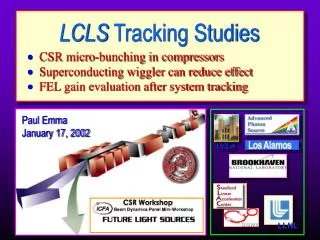
UCLA. LLNL. CSR micro-bunching in compressors Superconducting wiggler can reduce effect FEL gain evaluation after system tracking. LCLS Tracking Studies. Paul Emma January 17, 2002. CSR Workshop. LCLS Accelerator and Compressor Schematic. 250 MeV z 0.19 mm 1.8 %. 4.54 GeV

E N D
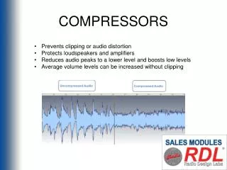
UCLA LLNL • CSR micro-bunching in compressors • Superconducting wiggler can reduce effect • FEL gain evaluation after system tracking LCLS Tracking Studies Paul Emma January 17, 2002 CSR Workshop
LCLS Accelerator and Compressor Schematic 250 MeV z 0.19 mm 1.8 % 4.54 GeV z 0.022 mm 0.76 % 14.35 GeV z 0.022 mm 0.02 % 7 MeV z 0.83 mm 0.2 % 150 MeV z 0.83 mm 0.10 % Linac-X L =0.6 m rf=180 rf gun Linac-1 L =9 m rf = -38° Linac-2 L =330 m rf = -43° Linac-3 L =550 m rf = -10° new Linac-0 L =6 m undulator L =120 m 21-1b 21-1d 21-3b 24-6d 25-1a 30-8c X ...existing linac BC-1 L =6 m R56= -36 mm BC-2 L =22 m R56= -22 mm DL-1 L =12 m R56 0 DL-2 L =66 m R56 = 0 SLAC linac tunnel undulator hall (12/01/01)
LCLS Linac Layout BC2 5.4 GeV BC1 0.25 GeV undulator 14.3 GeV
Compression Evolution using Elegant* before BC1 after BC1 E = 250 MeV sz 190 mm E = 250 MeV sz 830 mm under-compression of head & tail from 3rd-order term L2 wakes induce new 3rd-order correlation over-compression of head and tail before BC2 after BC2 E = 4.5 GeV sz 190 mm E = 4.5 GeV sz 22 mm * written by M. Borland, ANL/APS
3rd-order energy-time correlation from injector energy ‘chirp’ 2nd-order fit HEAD 3rd-order term remains… E0 = 150 MeV 1st, and 2nd-order correctable with S-band and X-band RF… 3rd-order term generated with space charge and l(s) in gun-to-linac drift (C. Limborg)
Smoothed Parmela dist. input to LCLS N = 2106 plus temporal smoothing at 150 MeV, before any bends
LCLS bunch tracked to start of BC2 cubic correlation term generates head/tail spikes at end of chicane CSR ON in upstream bends (BC1, etc) CSR OFF in upstream bends (BC1, etc) CSR in BC1 causes microbunching at entrance to BC2 …otherwise have smooth dist. at BC2 entrance
Superconducting Wiggler in LCLS… 5 cm 20 cm 4 T 20 cm 10 cm 90 cm SC wiggler BC2 chicane At BC2: E0 = 4.54 GeV sE/E0 3×10⁻⁵ Dex/ex0 7% At Undulator: E1 = 14.3 GeV sz0 195 mm sz1 22 mm (sz0/sz1)sE/E1 8.4×10⁻⁵ wiggler field limited by b-function Add Super-Conducting wiggler prior to BC2 to increase incoherent energy spread (×10)
Superconducting wiggler OFF SC-wiggler OFF SC-wiggler ON Using Stupakov CSR model (based on Saldin et. al.) and Elegant tracking CSR may still be over-estimated in present tracking
LCLS Distribution After BC2 Chicane (SC-wiggler ON, CSR ON in upstream bends) wiggler 310-5 incoherent energy spread sE/E0 = 0.726 % bunch head ss = 24.8 mm E0 = 4.54 GeV
LCLS Distribution After BC2 Chicane (SC-wiggler OFF, CSR ON in upstream bends) sE/E0 = 0.736 % 310-6 incoherent energy spread bunch head ss = 24.8 mm E0 = 4.54 GeV
LCLS Distribution After BC2 Chicane (SC-wiggler ON and CSR OFF in upstream bends) sE/E0 = 0.716 % wiggler 310-5 incoherent energy spread bunch head ss = 24.8 mm E0 = 4.54 GeV no CSR in upstream bends
LCLS Distribution After BC2 Chicane (SC-wiggler OFF, CSR OFF in upstream bends) sE/E0 = 0.736 % 310-6 incoherent energy spread bunch head ss = 24.8 mm E0 = 4.54 GeV no CSR in upstream bends
Final x-x Phase Space (LCLS input) e/e0 2.5
Transverse RF ON (V = 20 MV) Transverse RF deflector used to diagnose ‘slice’ emittance after BC2 screen at 6.2 MeV after BC2 with transverse-RF OFF
Sliced Beam After Injector and Linac Tracking gex gey osc-amp/s mismatch zx zy Ming-Xie method LG < 4 m
Summary • New awareness of CSR micro-bunching and new design optimization • Projected emittance doubles over linac, but slice parameters allow LG < 4 m • Projected emittance growth presents a diagnostics and tuning challenge (use transverse RF) • Stability studies and Genesis results (see M. Borland talk…)