Download
1 / 25
250 likes | 354 Views
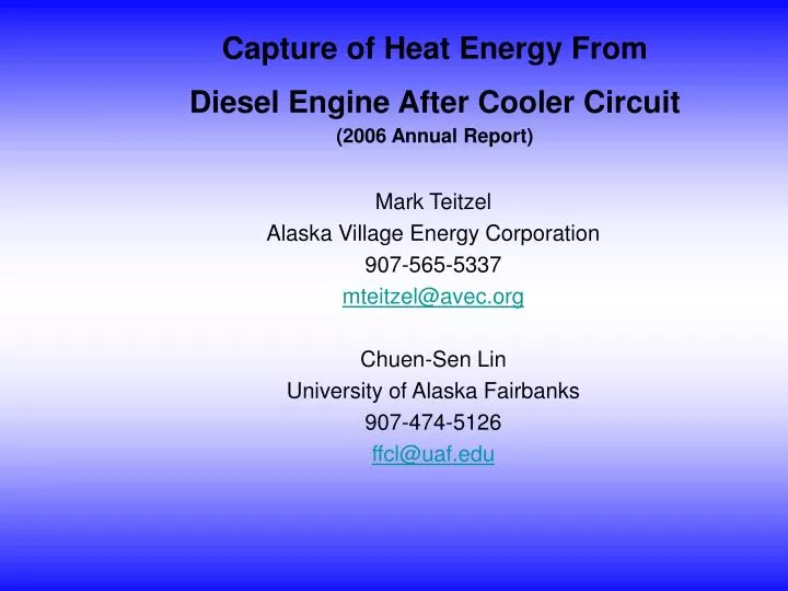
Mark Teitzel Alaska Village Energy Corporation 907-565-5337 mteitzel@avec.org Chuen-Sen Lin University of Alaska Fairbanks 907-474-5126 ffcl@uaf.edu. Capture of Heat Energy From Diesel Engine After Cooler Circuit (2006 Annual Report). Milestones. Design:

E N D
Mark Teitzel Alaska Village Energy Corporation 907-565-5337 mteitzel@avec.org Chuen-Sen Lin University of Alaska Fairbanks 907-474-5126 ffcl@uaf.edu Capture of Heat Energy From Diesel Engine After Cooler Circuit(2006 Annual Report)
Milestones • Design: Completion of exhaust heat recovery system design and an instrumentation plan. • Instrumentation and installation: Completion of installation of exhaust heat recovery system. Completion of instrumentation and calibration. • Testing and analysis: Exhaust condensate test and ph test Exhaust heat recovery system performance test result for three different applications. • Demonstration: Meetings and communication between AVEC and UAF.
Three Application Cases Future cogeneration market segments (Alaska Energy Plan- Cogeneration chapter) • Building with low temperature baseboard heating • Building with in floor radiant heating • Community water loop temperature maintenance • Residential micro cogeneration units (e.g. Stirling) • School cogeneration units (e.g. Diesel Generator)
Discussion of Data • Heat recovery system has worked as expected (consistent performance). • Temperature control valve has worked as expected. • Circuit setters effectively controlled the flow rates and pressure drops. • According to engine performance data (before and after the installation of the system), the system showed no noticeable influence on engine performance (e.g. P, T). • According to the experimental data of the last 100 hours of engine operation, the performance of heat exchanger was consistent (e.g. Q, T).
Discussion of Data (continued) • The temperatures at various locations of the shell (i.e. exhaust) side of the heat exchanger (including exhaust outlet temperature) were much higher than the dew point (40C) for all operation conditions. • Coolant flow rate was lower than expected (24 gpm versus 30 gpm). What would be the effect on heat recovery? • Heat exchanger efficiencies at different loads were between 71% to 78%, which were lower than expected. According to the insulation of the shell of the heat exchanger (4-in Kaowool), the heat loss to the environment from the exhaust should be about 1/3 of the current heat loss (15 kW). (Double check: [1] homemade insulation to the connection pipes. [2] the measurement instrument and procedure)
Discussion of Data (Continue) • For the first type of heat recovery application, the inlet coolant temperatures of the HX for all three loads were controlled to the desired value (around 76C). • For the second application, the inlet coolant temperatures of HX could not be controlled to the desired temperature (around 43C) except for the case of 50% load (or lower load). Reason: the load simulator (i.e. the unit heat) did not have enough surface area. This problem can be solved by increasing the load capacity of the load simulator.
Fouling Resistance(Experimental data quoted from Grillot’s Paper) Four different experimental cases Total soot injected for about 25 hours for each case Result:
Modified Performance of the Three Different Application Cases (with enough simulation load)
Percentage Difference in Heat Recovery Between Modified Case and the Original Case
Conclusion • Completion of design installation and instrumentation of the exhaust heat recovery system. • Study of the system performance: Control components (e.g. valve controller and circuit setters) worked as expected. System performance data indicated that HX system had no noticeable effect on engine performance. Based on HX performance data, soot thermal resistance has not changed much during the last 50 hours operation (need further investigation)
Conclusion (continue) Heating fuel saving per unit kW-hour for higher load was better but not critical. A relatively large amount of heat (compared to calculated result) dissipated into the surrounding. (Needs further investigation) According to measured temperature distribution of the shell side, corrosion may not become a problem for this exhaust HX. Lower coolant flow rate (24 gpm versus 30 gpm) may not affect the heat recovery rate significant (less than 1%). To lower the requirement of coolant inlet temperature will moderately increase the heat recovery rate. (Application 1 has the lowest heat recovery and application 3 has the highest).
Current Work • To continue performance data collection to further confirm the conclusion listed previously. • To develop a preliminary tool for heat exchanger system cost analysis. (Parameters: size, pressure drop, flow rate, capital and operation cost, etc.). • To propose some recommendations for exhaust heat exchanger design. • To continue collect data and conduct economic analysis.
Future work • Select a turbocharger compressed air heat exchanger and install the turbocharger after cooler heat exchanger system. • Conduct performance and economic analysis for the turbocharger heat recovery system. • Select a village as demonstration site for turbocharger after cooler heat recovery system field demonstration.
Acknowledgement • DOE • AETDL • AVEC • ICRC