Download
1 / 11
110 likes | 233 Views
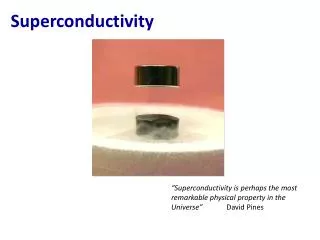
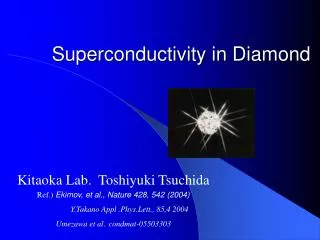
Superconductivity in iron-based layered oxy-pnictide compound. Kitaoka Laboratory. Hiroki Yamashita. H.Takahasi et al ; Nature 453 , 376 (2008). Kamihara ,Y et al ; J.Am.Chem.Soc. 130 , 3296 (2008). Contents. Introduction ・ History of superconductivity

E N D
Superconductivity in iron-based layered oxy-pnictide compound Kitaoka Laboratory Hiroki Yamashita H.Takahasi et al ; Nature 453 , 376 (2008) Kamihara ,Y et al ; J.Am.Chem.Soc. 130 , 3296 (2008)
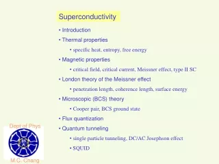
Contents • Introduction ・History of superconductivity ・Comparison between Fe-based system and High-Tc cuprate • Experiment • Summary cuprate:銅酸化物
1900 1920 1940 1960 1980 2000 2020 Year History of Superconductivity 200 High-Tc cuprate 1911 metal Iron-based system 163 Hg-Ba-Ca-Cu-O Superconductivity was discovered at a suitable pressure ( ) 150 Hg-Ba-Ca-Cu-O Tl-Ba-Ca-Cu-O 1986 Bi-Sr-Ca-Cu-O 100 High-Tc cuprate was discovered Transition temperature (K) Y-Ba-Cu-O 77 nitrogen temperature SmO F FeAs 50 0.9 0.11 2006 La-Ba-Cu-O MgB Iron-based system was discovered LaO F FeAs 2 0.11 0.89 Nb Pb Nb Ge NbN LaOFeP Hg NbC 0
La Cu O e- Sr2+ F Comparison (1) Doping mechanism High-Tc cuprate iron-based system charge reservoir layer Electron dope (O2- → F-) Hole dope (La3+ → Sr2+) ・ Layered structure (charge reservoir layer & conduction layer)
Temperature PM AF SC Temperature Hole density AF? electron density Comparison (2) Phase diagram Fe-based system High-TC cuprate ・Superconductivity appears by doping carriers. ・Superconducting transition related to a magnetic instability.
Experiment Electrical resistivity under various conditions 1.Carrier doping 2.Pressure 3.Substitution of La site Search for highest TC in Fe-As compounds
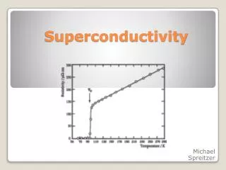
Resistivity in LaO1-xFxFeAs (x is amount of dope) x ? 26K X=0.11 (x) ・ Superconducting transition doesn’t occur by undoped sample. ・When x is 0.11,Tc is the maximam.
43K 43 43 26K Enhancementof Tc by Pressure in LaO0.89F0.11FeAs optimally doped TC increase below 3GPa , but TC decrease above 3GPa .
Maximum of Tc Effect of substitution at La-site substitution atomic radiusdecrease 54K Nd Pr Sm Ce 26K Gd La Atomic radius decrease
Suppression of Tc by Pressure in NdFeAsO0.6 As increasing pressure , TC decrease
Summary • New material base for high-TC superconductivity was discovered in Fe-As compound. • Superconductivity realizes by doping the carrier. • TC can be tuned by applying pressure or substitution at La-site. 54K 26K