Download
1 / 1
10 likes | 179 Views
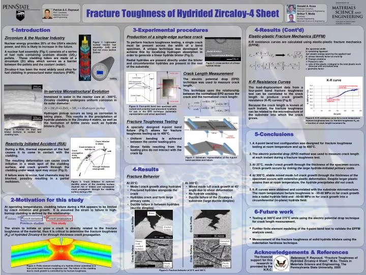
Patrick A.C. Raynaud PhD. Candidate Materials Science and Engineering. Donald A. Koss Professor Emeritus Materials Science & Engineering Arthur T. Motta Professor Nuclear Engineering Materials Science & Engineering. Radial direction. Circumferential direction.

E N D
Patrick A.C. Raynaud PhD. Candidate Materials Science and Engineering Donald A. Koss Professor Emeritus Materials Science & Engineering Arthur T. Motta Professor Nuclear Engineering Materials Science & Engineering Radial direction Circumferential direction Figure 1: Light-water nuclear reactor fuel assembly (left) and fuel rod cross section (below) 190m Figure 5: cross-section of a linear hydride blister U02 cladding 250m 500m Figure 2: Hydride rim (top) and blister (bottom) in nuclear fuel cladding tube. Crack initiation in blister Crack initiation in hydride rim Crack propagation along hydrides Through thickness crack growth Figure 3: Crack initiation in reduced ductility zones of the cladding surface (hydride rim or blister) and subsequent crack propagation through the cladding surface during a RIA Blister Cracked hydrides B17 190m Crack Profile Crack Profile Primary voids (cracked hydrides) Uncracked hydrides Crack Surface Crack Surface Ductile dimples Ductile dimples Fracture Toughness of Hydrided Zircaloy-4 Sheet 1-Introduction 3-Experimental procedures 4-Results (Cont’d) Elastic-plastic Fracture Mechanics (EPFM) Production of a single-edge surface crack To perform fracture toughness testing, a single crack must be present across the width of a bend specimen. A unique technique was developed to achieve this by localizing hydrogen absorption in order to generate a linear hydride blister (Fig.5). Radial hydrides are present directly under the blister and circumferential hydrides are present in the rest of the substrate Zirconium & the Nuclear Industry Nuclear energy provides 20% of the USA’s electric power, and this is likely to increase in the future. A nuclear fuel assembly (Fig.1) consists of a series of fuel rods containing uranium dioxide (UO2) pellets. These cladding tubes are made of a zirconium (Zr) alloy which serves as a barrier between the pellets and the coolant (water). Zircaloy-4 has been the most widely used alloy for fuel cladding in pressurized water reactors (PWR). K-R resistance curves are calculated using elastic-plastic fracture mechanics (EPFM): Bn: specimen width b: remaining ligament Apl: plastic energy spent by the applied load K: stress intensity factor at crack tip E: Young’s modulus ν: Poisson’s ratio η: ratio of the plastic J-integral to the total plastic work done per unit uncracked area : geometry factor Crack Length Measurement The electric potential drop (EPD) technique was used to measure crack length. This technique uses the relationship between the normalized EPD across the crack and the normalized crack length: K-R Resistance Curves The load-displacement data from a four-point bend fracture toughness test can be correlated to the crack length to produce crack growth resistance (K-R) curves (Fig.9) Because the crack length is known at each instant, the fracture toughness can be related to the microstructure of the substrate into which the crack grows. In-service Microstructural Evolution Immersed in water in the reactor core at ~300°C, Zircaloy cladding undergoes uniform corrosion in its outer diameter: Hydrogen pickup occurs as long as corrosion is taking place. This results in the precipitation of hydride platelets in the Zircaloy-4 matrix, as well as the formation of brittle zones such as hydride blisters (Fig.2). Figure 6: Four-point bend test specimen with current and potential lead placement locations for use in the EPD technique (schematic representation and actual specimen) Figure 9: K-R resistance curve for a room temperature fracture toughness test, i.e. fracture toughness KQ as a function of crack length increment δa. • Fracture Toughness Testing • A specially designed 4-point bend fixture (Fig.7) allows for fracture toughness testing up to 400°C. • Uniform bending is achieved between the center loading-pins • Stress fields resulting from the loading pins do not interact with the crack tip 5-Conclusions • A 4-point bend test configuration was designed for fracture toughness testing at room temperature and up to 400°C. • The electric potential drop (EPD) method was used to measure crack length at each instant during a fracture toughness test. • At 25°C, mode I crack growth through the thickness of the specimen occurs. Crack growth occurs by linking the large hydride-initiated primary voids. • At 300°C, stable mixed mode I+II crack growth through the thickness of the specimen occurs with extensive plastic deformation. Despite larger plastic strains than at room temperature, the hydride precipitates did not crack. • K-R curves were obtained and correlated with the substrate microstructure. The room temperature facture toughness is ~30-40 MPa√m for crack growth into a radial hydride field and ~40-60 MPa√m for crack growth into a circumferential (in-plane) hydride field. Reactivity Initiated Accident (RIA) During a RIA, thermal expansion of the fuel causes it to come in contact with the cladding. The resulting deformation can cause crack initiation in a weak spot of the cladding surface, and crack growth through the cladding under weak spot may occur (Fig.3). If failure were to occur, fuel channels may be blocked, possibly resulting in a partial meltdown. Figure 7: Schematic representation of the 4-point bend specimen and fixture. 4-Results Fracture Behavior • At 25°C: • Mode I crack growth along hydrides • Fractured hydrides alongside the crack • Hydrides crack and form large primary voids • Ductile failure in between hydrides (ductile dimples) • At 300°C: • Mixed mode I+II crack growth at 45° angle due to shear deformation • No hydride cracking • Ductile failure of the Zircaloy-4 substrate (large ductile dimples) 2-Motivation for this study At operating temperatures, cladding failure during a RIA appears to be limited by crack initiation and growth. It is assumed the strain to failure in high-burnup cladding is defined by the relationship: Previous studiesThis study The strain to initiate or grow a crack is directly related to the fracture toughness of the material, thus it is critical to determine the fracture toughness (KQ) of hydrided Zircaloy-4 for through thickness crack propagation. 6-Future work • Testing at 300°C and 375°C while using the electric potential drop technique for crack length measurement. • Further finite element modeling of the 4-point bend test to validate the EPFM analysis used. • Measurement of the fracture toughness of solid hydride blisters using the indentation hardness technique. Acknowledgements & References The financial support for this research is provided by the N.R.C. Reference: P. Raynaud, “Fracture Toughness of Hydrided Zircaloy-4 Sheet,” M.Sc. Thesis in Materials Science and Engineering, The Pennsylvania State University, 2005 Figure 4: Finite element modeling of a hydride blister submitted to a four point bend fracture toughness test. The failure of the cladding due to crack growth is controlled by its fracture toughness. Figure 8: Fracture behavior at 25°C and 300°C.