Download
1 / 31
310 likes | 451 Views
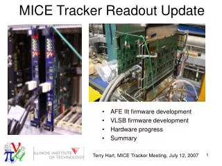
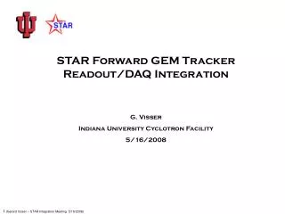
STAR Forward GEM Tracker Readout/DAQ/Controls Subsystem. Renee Fatemi University of Kentucky John T. Anderson, Dave Underwood Argonne National Laboratory Gerard Visser Indiana University Cyclotron Facility Paul Nord Valparaiso University

E N D
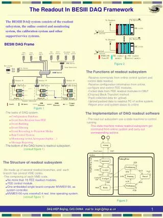
STAR Forward GEM Tracker Readout/DAQ/Controls Subsystem Renee Fatemi University of Kentucky John T. Anderson, Dave Underwood Argonne National Laboratory Gerard Visser Indiana University Cyclotron Facility Paul Nord Valparaiso University (and the STAR DAQ group, T. Ljubicic, J. Landgraf, BNL) 6/14/2010
Simplified outline of readout/DAQ… and this presentation… Detector You will hear about: (in WSC) • Detailed design choices in most of these labeled elements • How we move the stored analog data from APV chips • How we digitize it • How we zero suppress, buffer, and deliver it to DAQ software • Care & feeding of FEE (power, clock, trigger, I2C) • Safety, reliability, serviceability • Current status • Schedule of remaining work • Budget and costs FEE HV (DAQ room) PC (FGT DAQ) Cables, connectors, patch panel STAR Trigger (TCD) HVPS ARM ARC (electronics platform (south)) Crate
Transporting the APV readout signals 1 1 10 1 0 1 0 1 0 01 The APV “digital” header provides a convenient test pattern! We expect to actively use this for calibration, and at least as a noise check. If the APV analog signals are seen with noise >> “digital” signal noise, then the cable / readout system is not contributing any significant noise. This goal is met! APV ONLY – 110 Ω LOAD FGT FEE Assy. 3.3 m (16 ns) 17 m (73 ns) +/- 4mA twisted pair twisted pair Isig -/+ 4mA GND (TPC) Actual ground noise at STAR (TPC west w.r.t. platform) This cable diagram shows only the one analog output and the ground reference (from TPC ground to the detector). Actual connections include of course 10 outputs, control signals and power. (10x scale) 0.5V peak ∆VGND
Patch panel Approximate radius of WSC Approximate location / size of FGT patch panel (2 ea.) Typical FGT cable route. With (mainly TPC) cables in sector gap “channels”.
Clocking scheme • APV sample clock should be synchronous to bunch crossing clock (“RHIC strobe”). This gives best amplitude measurement w/o need for a timing fit and correction. • 4× RS is close to APV nominal sample frequency (40 MHz) so we use that. 3× RS would also be a reasonable option. • APV offers choice of readout clock = sample clock or sample clock/2 • The half-rate output (2× RS) is quite sufficient for FGT and other APV applications in STAR: 3-pt readout requires 420/(18.766 MHz) = 22.4 µs which fits very well with the calorimeter deadtime (~27 µs except BSMD). • In the half-rate mode the half-cycle readout phase is defined by the I2C address of the APV chip. We are careful to choose address values to keep all readouts aligned, this allows maximal settling of crosstalk in the signal cable prior to ADC sampling. • Clock adjustment/distribution: • incoming clock from trigger (TCD) common to all FGT. This clock has adjustable phase, useful for global timing scan. • multiplied (4×) clock with phase control per FEE group (10(12) chips) (most likely will use identical settings but it is convenient to provide individual PS circuitry) • the 4× clock also to ADC’s with phase control per FEE group. This phase control is tuned to compensate for cable length. • changes in beam timing, etc., are compensated globally at STAR, or if necessary with FGT TCD phase control
Choosing the ADC • Requirements • ≥40 MSPS • 12 bits (for >10 bits effective resolution) • input bandwidth sufficient for 20 MHz stepped waveform • Goals • high density packaging and appropriate pinout • single supply • low power • serial interface preferable Best options at present Selected Quad 40MSPS, 11.7 ENOB @ 30 MHz, 50 mW/ch Newly available (Q1 2010)
At higher supply voltages, one can get away with single-ended drive. Not here, with a 1.8 V supply ADC. • Transformer coupling with digital DC restoration was considered, but this is too hard. LF cutoff is nonlinear and temperature sensitive. Rejected. • Driver requirement: Faster than filter response, low power, differential output. DC accuracy is not that significant. Prefer to use existing power rails i.e. +1.8, +/-5.5 for improved layout/performance. • Filter requirement: Minimum bandwidth while providing 6 ns flat sampling window to allow for cable skew and clock jitter/drift. Driving the ADC +1.8 (ADC) From line receiver Implementation: (Several other low power drivers prototyped. There exist many others not low power, not considered.) To ADC +/- 5.5V power, 38 mW Differential driver alone, response and imbalance 16 ns flat (<0.1%) sampling window (driver/filter test pulse response) Out + Fast test pulse 53.3 ns APV read cycle Out CM Out -
Driving clock and trigger to the FEE • LVDS with transformer coupling (at ARM) to maintain high common-mode impedance to the line • precision line receiver buffers signals before presenting to APV • DC offset applied to TRIG line, which works since duty cycle is guaranteed low (BUSY >> 25 ns) 33 m cable (1424A), P6247 probe
Power to FEE • Floating output low noise push-pull converter 5V to ≈3V • Remote regulation to 1.8V • This is a small modification of circuit successfully used on another project (GlueX ADC) • Test board will be fabricated
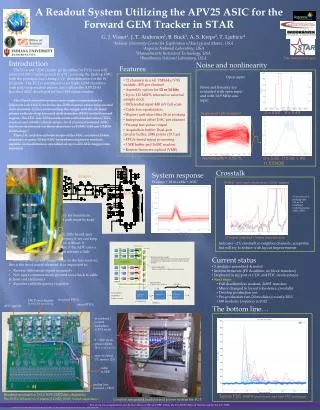
APV / cable / ARM frontend prototype results APV header data w/ equalization & shaping filter Last header bit For reference: unequalized response 2nd analog level Cable & ARM do not limit resolution
ARM and ARC dataflow Backplane 4096 buffers (128 MB DDR SDRAM) Acquisition buffer Channel output fifo 512 × 12 1024 ×33 Buffer write fifo Output fifo ADC 8192 × 33 1024 × 33 SIU 32 kB buffer Take table Token fifo 4096 × 12 Other channels ≥ ? Threshold table Covered by deterministic busy algorithm in TCD Never busy (by construction)
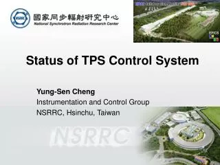
Readout system integration schematic (simplified) Measured cable run 55 feet [ WSC → TPC sec 2/3 boundary → sec 2/3 tray out of magnet → 2nd level platform ceiling tray → 2C7/8/9 ] FEE cables Rear entry via 6U × 80mm transition board FGT Cables 24 FEE signal 24 power & remote sense 24 HV coax 2+2 8 Cable break patch panel located just outside of west support cylinder, on TPC wheel. This point also serves as FGT detector ground tie (to TPC wheel). Internal FEE signal cables: custom low-mass aluminum design with silicone & FEP extruded insulation Internal HV cables: Thin coax (5kV per CERN/DESY spec) Wiener MPOD controller (1×) ISEG 8 ch HV module (3×) −5 kV Wiener crate (1×) (FGT custom) 6U × 220mm cards 208 V 1φ DDL fiber ethernet trig/clk SGIS (to kill all FGT power) ARM (12×) APV Readout Module 2×(12×APV) each [IUCF] ARC (2×) APV Readout Controller 6×ARM each [ANL]
Readout / HV crate • three HV slots, one HV/crate controller (MPOD) • two readout segments each with 7-slot CPCI backplane (custom bus usage not PCI) • six readout board (ARM) slots • one readout controller (ARC) slot • all modules 6U × 220 mm • PS ratings 24 V @ 23 A for HV modules, 2 × ( 5 V @ 115 A ) for readout • we expect to run about 55% of this • controls via ethernet/SNMP w/ EPICS support • ordered/received 1 + 1 spare, presently at ANL and IUCF
ARM (APV Readout Module) Handles 2 groups of up to 12 APV each FGT will use 2 groups of 10 APV FEE power 1.8V isolated remote-regulating supply “P1” readout backplane to ARC (CPCI) FPGA (3×) P2 96-pin passthrough FEE signal/power connections ADC Driver Filter Line RX Currently working on ADC footprint & support component placement
ARC (APV Readout Controller) LEDs “P1” readout backplane to 6× ARM (CPCI) SIU (optical link) Ethernet JTAG FPGA (XC3S700A) Trigger DDR memory 128 MB (main data buffer) Auxiliary NIM I/O
Data size and rates • APV data frame consists of 140 datapoints (12 APV-header + 128 channels) • For the typical 3-pt (per channel) readout, that’s 420 datapoints • Take 10 pre, 10 post to monitor baseline / eq. 440 datapoints • NZS fixed-array format, 2 bytes each (1.5 significant, could be packed) • ARM supports 24 APV 21120 bytes (raw) per event per ARM + 32 byte header • ARC 126912 bytes (raw) per event +64 byte header = 126976 bytes • SIU bandwidth 200 MB/s @ 50 MHz max1.58 kHz trigger rate non-ZS • Crate backplane bandwidth 120 MB/s @ 30 MHz max 945 Hz trigger rate non-ZS • or by packing the data over backplane, then max 1.26 kHz non-ZS • for 1-pt readout, take 160 points, then SIU limit 4.3 kHz, backplane limit 2.59 kHz • To go beyond these rates, we will do ZS onboard ARM. Arbitrary neighbors included (defined by table). • ZS event size limited to 32 kB (occupancy limited to ≈25%). For 4096-event buffer use 128 MB (SDRAM).
DAQ hardware and software • Hardware: 2 DDL SIU, 1 DDL D-RORC, 1 linux PC w/ PCI-X, 2 duplex fiber runs between 2C9 and DAQ room. • We have all this hardware, installation is nearly complete, will be finished this summer • Software: • FGT is present in STAR run control • FGT is present in DAQ monitoring • FGT DAQ front-end software is in place • Generic “DAQ Reader” handles FGT • Specific FGT unpacking software and online monitoring software to be completed once the readout firmware and FGT channel mapping and geometry are finalized.
FGT slow controls – general overview and integration with STAR EPICS-based control system Standard in STAR Integrates with STAR Alarms system and Logger Variable naming convention FGT_* IOC setup for Slow Controls on dedicated computer FEE (controls & power) – will be set and queried through standard EPICS calls Communication via ethernet through EPICS CA get/set calls DAQ system software provides interface to FEE/readout hardware via DDL optical link During run, readout hardware generates periodic status “events” rather than accepting control transactions Setup parameters, e.g. APV registers, timing controls, are handled (and archived) through STAR run control framework GEM HV & Readout crate LV Controlled via ethernet through standard SNMP calls SNMP library provided by Wiener Using EPICS code developed by STAR TOF group Prototype FGT controls GUI is operational with crate/HV system at IUCF
Safety… • is taken into account in the design process • Materials choices (e.g., cable to UL-1581 vertical tray requirements). • Voltages and currents within connector and wire/cable ratings. • Incoming power fused on all boards where source may deliver a larger fault current. Fuses of course are rated to interrupt maximum expected fault. • Outgoing power (to cables) fused or inherently limited on all boards. • FEE power and detector bias supplies sized appropriately, not excessive power • Where ground break is needed for (non-floating) HV supplies, a safety resistor tie is used. Generally meaning 100 Ω leaded carbon-composition resistor. • Cables will be routed neatly and not to present hazards to personnel or other equipment (snagging, tripping, etc.). • The FGT had a preliminary C-AD Experimental Safety Review on 9/2/2009. Relevant (electronics) action items were: • What is the expected maximum temperature inside the [WSC] when the air flow is off? Assess if an interlock is required. • • Test the high voltage distribution system to 2x (operating voltage) + 1000 V • • Check the Weiner HV and crate and secure [C-AD] approval in lieu of NRTL. • • The Wiener HV supplies will be voltage limited to 5 kV. Add a sticker on each unit prior to use to assure compliance with the SHV connector [rating]. • • Provide a sample of the custom signal and power cable as well as the special HV cable to J. Levesque to approve for flammability concerns. • • Review the ARC and ARM modules after design is completed. All good / anticipated points. All being addressed.
Budget, costs to date, current projections (equipment & materials)
Completed tasks • APV long cable readout test • Rack / cable route assignment at STAR • Crate specification, procurement, received • ARM – ARC interface defined • GEM HV PS selection, procurement, received • Custom cable specification, procurement, received 1 of 2 types • Cable routing at detector, power budget at detector; mechanical design is proceeding • Service installation at STAR: fibers, ethernet, AC (nearly done), smoke det., water/air heat exchanger • DAQ PC, D-RORC, DAQ & run control software is installed and ready to run • Event buffering & transmission scheme (1st deployed in BSMD) • ARC design, bare board fabrication ~now
Highlight of tasks and schedule to completion Evaluation & revisions if required for ARC printed circuit board. Firmware design for ARC. FEE power supply & line interface test pcb & evaluation. Complete detailed schematic and layout of ARM printed circuit board. Fabricate and assemble 3 units. Design ARM rear transition board and patch panel printed circuit boards. Includes final selection of connectors and mechanical integration drawings & hardware. Fabricate all. Assemble cables and connectors. Evaluation & revisions if required for ARM printed circuit board. Fabricate & assemble 16 – 18 final ARM. Firmware design for ARM. Rack & crate installation at STAR. Partial cable installation. Standalone STAR DAQ functional with ARC/ARM. FGT beam test activities. Specific data unpacking, online plots, slow controls milestone. FGT final C-AD safety review. Installation at 1006 Assembly Bldg to support FGT/WSC tests. Complete installation at STAR. Commissioning. 7/10 – 9/10 7/10 – 11/10 7/10 8/10 9/10 8/10 9/10 – 1/11 8/10 – 1/11 10/10 – 3/11 8/10 – 1/11 8/10 – 11/10 10/10 11/10 2/11 4/11 4/11 8/11 11/11 – 2/12
Closing remarks • The Readout / DAQ / Controls subsystem provides a modern, fast, reliable, safe, efficient APV chip readout capability for the Forward GEM Tracker in STAR. (With potential other STAR applications to IST, PP2PP.) • We are leveraging ideas and experience from other STAR detectors particularly the EEMC and BEMC, and from other work. • Although there are some detail design tasks to be completed before production, all concepts and interfaces are worked out and expected to be stable. Many have been prototyped. • Crates, custom cables, and ARC module are already fabricated or in fabrication now. • We will be in a position to fabricate the remaining hardware soon. • We will be ready for the test beam and for summer 2011 installation, within budget. Thank you…
Overview I: signal path schematic +1.25 V APV25-S1 ASIC Drifting electron cloud 8 mA p-p Sample clock 4x RHIC strobe 37.532 MHz -1.25 V About 55 feet of cable AD8129 High impedance differential receiver -HV (GEM3 bottom) FPGA w/ SRAM Sampling filter 12 bit ADC Crate backplane ARC module (to DAQ) Minimize common-mode currents Cable frequency response equalization circuit
Slide from safety review (BNL 9/2/2009) Overview II: GEM quadrant assembly and electrical connections 3 4 Terminator board FR-4, 32 x 38 x 0.8 mm FGT cables to platform 2 FEE board (2x) FR-4, 259 x 53 x 1.6 mm Total power 6.9 W per quadrant STAR TPC aluminum structural parts (STAR system ground) Ground wire 18AWG stranded 1 2 LV & signal patch Bud #PN-1320-C 64 x 58 x 35 mm Polycarbonate, UL 94HB “Connector” board FR-4, 65 x 45 x 0.8 mm Bias divider board FR-4, 20 x 275 x 0.8 mm GEM bias patch SHV cable connectors Anode strip board and ground plane
ALICE Detector Data Link – SIU & D-RORC • Now in use at STAR for • TPX (TPC upgrade for DAQ1000) • BTOW † • ETOW † • TOF • ESMD † • BSMD † • Standard data link hardware allows STAR operations to maintain a pool of spares • STAR-standard API exists and is being maintained by TonkoLjubicic for integration of D-RORC into STAR DAQ • Works with commodity Intel-architecture PC’s running linux SIU Developed and extensively tested by CERN for ALICE Commercially available (CERNTech) Event-driven data transfers Bidirectional control transfers 200 MB/s per SIU Simple protocol, no CPU is necessary to run SIU at the detector D-RORC is PCI-X master, writes data directly to a (pre-allocated locked down) main memory buffer D-RORC ( †By FGT personnel )
Slide from safety review (BNL 9/2/2009) WSC field-shaping bias system Glassman EH10N10, -10 kV w/ current limit Fixed operating point tbd, expect approximately -5.5 kV “Protection: Automatic current regulation protects the power supply against all overload conditions, including arcs and short circuits. Fuses, surge limiting resistors, and low energy components provide the ultimate protection. Remote Controls: Common, +10 volt reference, interlock, current monitor, current program, voltage monitor, voltage program, HV enable/disable, and ground provided on a rear panel terminal block. External Interlock: Open off, close on.” Becomes a new permit to TPC cathode Reynolds HV cable with series 531 connectors. Rated 10 kV operation, 100% tested to 15 kV, commercially assembled. Length approximately 50 feet, tbd. Mating connector (Reynolds series 531) is an integral bonded part of WSC – TPC mechanical interface structure. Bias voltage runs in from there to shroud electrode on 20kV silicone high voltage wire.