Download
1 / 44
440 likes | 564 Views
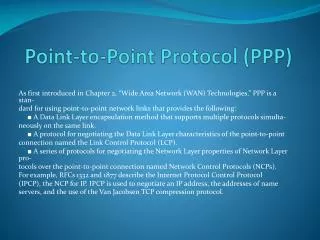
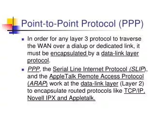
Chapter 2 Point-to-Point Protocol (PPP) Part-I. Point-to-Point Protocol (PPP). Introducing Serial Communications. How Does Serial Communication Work?. Most PCs have both serial and parallel ports. Electricity can only move at one speed.

E N D
Chapter 2 Point-to-Point Protocol(PPP) Part-I
Point-to-Point Protocol (PPP) Introducing Serial Communications
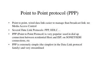
How Does Serial Communication Work? Most PCs have both serial and parallel ports. Electricity can only move at one speed. Data is compressed so that less bits are necessary and then require less time on the wire, or transmit the bits simultaneously. Computers make use of relatively short parallel connections betweeninterior components. Use a serial bus to convert signals for most external communications.
How Does Serial Communication Work? Serial – one bit at a time Two wires to send and receive. Eight wires to send and receive. Parallel – bits over more wires simultaneously.
In both cases, the remaining wires are used for control signals. The parallel link theoretically transfers data eight times faster than a serial connection. In reality, it is often the case that serial links can be clocked considerably faster than parallel links, and they achieve a higher data rate. Two factors affect parallel communications: Clock Skew. Crosstalk Interference. How Does Serial Communication Work?
Parallel Communications Clock Skew: In a parallel connection, it is wrong to assume that the 8 bits leaving the sender at the same time arrive at the receiver at the same time. In reality, some of the bits get there later than others. Not trivial to overcome. Read, wait, wait adds time. How Does Serial Communication Work?
Parallel Communications Crosstalk Interference: In a parallel connection ,the wires are physically bundled in a parallel cable. The possibility of crosstalk across the wires requires more processing. How Does Serial Communication Work?
Serial Communication: Clock skew is not a factor because most serial links do not need the same type of parallel clocking. Crosstalk Interference is minimized since serial cables have fewer wires and network devices transmit serial communications at higher, more efficient frequencies. How Does Serial Communication Work? X X
Serial Communication Standards Receive: Same protocol used tode-capsulate the frame. Frame transmitted bit by bit on a physical medium to the WAN. Send: Data encapsulated using a specific WAN protocol.
Three key serialcommunication standards: RS-232C or newer RS-422, RS-423: Most serial ports onpersonal computersconform to the RS-232C standards. Both 9-pin and 25-pin connectors are used. A serial port is a general-purpose interface that can be used for almost any type of device, including modems, mice, and printers. Serial Communication Standards
Three key serialcommunication standards: V.35: V.35 is the interfacestandard used by mostrouters and DSUs thatconnect to T1 carriers. V.35 cables arehigh-speed, serialassemblies designed to support higher data rates and connectivity between DTEs and DCEs over digital lines. Serial Communication Standards
Three key serialcommunication standards: HSSI: A High-SpeedSerial Interfacesupportstransmission ratesup to 52 Mb/s. Engineers use HSSI to connect routers on LANs with WANs over high-speed lines such as T3 lines. Serial Communication Standards
Time Division Multiplexing Remember that aWAN connectionnormally uses aprovider’s network. The internal path isshared by severalconversations orWAN connections. Time Division Multiplexing (TDM) is used to give each conversation a share of the connection in turn. TDM assures that a fixed capacity connection is made available to the subscriber.
Time-Division Multiplexing (TDM) is the transmission of several sources of information using one common channel, or signal, and then the reconstruction of the original streams at the remote end. TDM is a physical layer concept. It has no regard of the information that is being multiplexed. Time Division Multiplexing
TDM Operation: Each deviceattached to theMUX is assigneda specifictime slot. 8 bits from each time slot are read and are used to build the frame. If there is nothing to send from that time slot, it still takes up space in the frame (null characters). At the receiving end, the frame is de-capsulated and time slot data is forwarded to the appropriate device. A technique called bit interleaving keeps track of the sequence of the bits so that they can be efficiently reassembled into their original form. Time Division Multiplexing
Statistical Time Division Multiplexing Remember that TDMwill fill an empty timeslot with nullcharacters if there isno data. Inefficient. Statistical Time Division Multiplexing (STDM) was developed to overcome this inefficiency. It uses a variable time slot length allowing channels to compete for any free slot space. It employs buffer memory to temporarily store the data and requires each transmission to carry identification information (a channel identifier).
TDM and STDM Examples Integrated Services Digital Network (ISDN)…..TDM 10 time slots
Synchronous Optical Networking (SONET)…..STDM Synchronous Digital Hierarchy (SDH): TDM and STDM Examples Output as a single stream on fiber. Bit rate = 4 x n Multiple (n)input channels. Optically multiplexed and modulated to 4 times the input bit rate.
T-carrier Hierarchy: The original unit used in multiplexing telephone calls is 64 kb/s, which represents one phone call. It is referred to as a DS-0 or DS0 (digital signal level zero). T1: In North America, 24 DS0 units are multiplexed using TDM into a higher bit-rate signal with an aggregate speed of 1.544 Mb/s for transmission over T1 lines. E1: Outside North America, 32 DS0 units are multiplexed for E1 transmission at 2.048 Mb/s. TDM and STDM Examples
T-Carrier Hierarchy: While it is common to refer to a 1.544 Mb/s transmission as a T1, it is more correct to refer to it as DS1. T-carrier refers to the bundling of DS0s. TDM and STDM Examples
T-Carrier Hierarchy: TDM and STDM Examples
Demarcation Point (Demarc) Deregulation forced telephone companies to unbundle their local loop infrastructure to allow other suppliers to provide equipment and services. The demarcation point marks the point where your network interfaces with the network owned by another organization. Subscriber owned and maintained. Provider This YOUR responsibility, including the wiring.
DTE and DCE DTE: Data Terminal Equipment Router, Terminal, PC, Printer, Fax Machine DCE: Data Communications Equipment CSU/DSU, Modem (Internal or External) A serial connection has a DTE device at one end of the connection and a DCE device at the other end. The connection between the two DCE devices is the WAN service provider transmission network.
DCE and DTE Cable Standards: Originally, the concept of DCEs and DTEs was based on two types of equipment: Terminal equipment that generated or received data. Communication equipment that only relayed data. While the reasons are no longer significant, we are left with two different types of cables: One for connecting a DTE to a DCE. Another for connecting two DTEs directly to each other. DTE and DCE
DCE and DTE Cable Standards: RS232 Standard: The original RS-232 standard only defined the connection of DTEs with DCEs (modems). If you want to connect two DTEs, such as two computers or two routers in the lab, a special cable called a null modem eliminates the need for a DCE. DTE and DCE
DCE and DTE Cable Standards: DTE and DCE
DCE and DTE Cable Standards: DTE and DCE Router DB-60 Connection Router Smart Serial
DCE and DTE Cable Standards: In the lab: DTE and DCE
HDLC Encapsulation Layer 2 WAN Encapsulation Protocols:
High-level Data Link Control (HDLC): HDLC is a bit-oriented, synchronous, Data Link layer protocol developed by the International Organization for Standardization (ISO). Developed from IBM’s Synchronous Data Link Control (SDLC) standard proposed in the 1970s. Provides both connection-oriented and connectionless service. Defines a Layer 2 framing structure that allows for flow control and error control through the use of acknowledgments. Uses a frame delimiter, or flag, to mark the beginning and the end of each frame. HDLC Encapsulation
High-level Data Link Control (HDLC): Cisco has developed an extension to the HLDC protocol to solve an inability to provide multiprotocol support. Cisco HLDC is proprietary and is the default encapsulation on a Cisco device WAN port. Cisco HDLC frames contain a field for identifying the network protocol being encapsulated. HDLC Encapsulation
Standard/Cisco HDLC Frame Types: HDLC Encapsulation Three frame types but not important to know contents.
HDLC Frame Fields: Flag: The flag field initiates and terminates error checking. The frame always starts and ends with an 8-bit flag field. The bit pattern is 01111110. If the pattern occurs in the data after the flag, zero-bit insertion is used to ensure data integrity. ‘0’ bit is inserted after every occurrence of five ‘1’ bits. Sender inserts – receiver removes. HDLC Encapsulation
Cisco Proprietary HDLC Frame - (cHDLC) 0x0F for Unicast 0x8F for Broadcast packets. The Control field is always set to zero. The Protocol Code field is used to specify the protocol type encapsulated within the HDLC frame.
Configuring HDLC Encapsulation Cisco HDLC is the default encapsulation method used by Cisco devices on synchronous serial lines. You use Cisco HDLC as a point-to-point protocol on leased lines between two Cisco devices. If you are connecting to a non-Cisco device, use synchronous PPP. Router(config)#interface s0/2/0 Router(config-if)#encapsulation hdlc
Troubleshooting a Serial interface For data to move across a serial link, both the interface (Layer 1) and the line protocol (Layer 2) must be in the “up” state. Layer 1: The Layer 1 physical interface must be up before the logical Layer 2 protocol can come up. When the provider’s circuit becomes active, a clocking or carrier detect signal is sent to the CSU/DSU. The CSU/DSU recognizes that the line is active and sends the same signal to the DTE device. You will see this signal referenced as CD or DCD either on a LED (CSU/DSU or modem) or in a status display (DCD=up).
For data to move across a serial link, both the interface (Layer 1) and the line protocol (Layer 2) must be in the “up” state. Layer 2: Once the physical link is active, the Layer 2 protocol can begin it’s connection process. The Layer 2 connect will depend upon the line protocol in use. (Frame Relay / PPP / X.25) Additionally, keepalive packets are sent by the remote router on a regular basis (usually every 10 seconds) to ensure that the link is still usable. Once the Layer 2 connection is made, the line protocol is up. Troubleshooting a Serial interface
show interfaces serial command: Will show the status of all serial links on the router. The interface status line has six possible states: serial x is up, line protocol is up serial x is down, line protocol is down serial x is up, line protocol is down serial x is up, line protocol is up (looped) serial x is up, line protocol is down (disabled) serial x is administratively down, line protocol is down Troubleshooting a Serial interface
serial x is up, line protocol is up Proper status for the link. Troubleshooting a Serial interface
serial x is down, line protocol is down The router is not sensing the carrier detect signal. Possible Causes: Router cable is faulty or incorrect. Router has a faulty router interface. CSU/DSU hardware failure. Provider’s circuit is down or it is not connected to the CSU/DSU. Troubleshooting a Serial interface
serial x is up, line protocol is down A local or remote router is not reachable. Possible Causes: Router not receiving/sending keepalive packets. Local router has a faulty router interface. Local router cable is faulty. Local CSU/DSU not providing the DCD signal. Local CSU/DSU hardware failure. Provider’s circuit is down. One of the LOCAL conditions above exist at the remote end of the link. Troubleshooting a Serial interface
serial x is up, line protocol is up (looped) A loop exists in the circuit. The sequence number in the keepalive packet changes to a random number when a loop is detected. If the same number is returned, a loop exists. Possible Causes: Misconfigured loopback interface. CSU/DSU manually set in loopback mode. CSU/DSU remotely set in loopback mode by the provider. Troubleshooting a Serial interface
serial x is up, line protocol is down (disabled) A high error rate exists. Possible Causes: A high error rate exists on the provider’s circuit due to a provider problem. CSU/DSU hardware problem. Router interface hardware problem. Troubleshooting a Serial interface
serial x is administratively down, line protocol is down Router configuration problem. Possible Causes: Duplicate IP Address exists. The no shutdown command has not been entered for the serial interface. Troubleshooting a Serial interface P.S. I tried to get Cisco to change the message to serial x is administratively down, line protocol is down, DUMBASS but they said that while they agreed, they couldn’tpossibly make that change…..