Download
1 / 37
370 likes | 375 Views
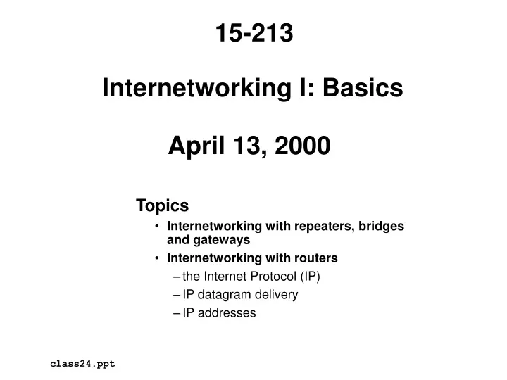
15-213. Internetworking I: Basics April 13, 2000. Topics Internetworking with repeaters, bridges and gateways Internetworking with routers the Internet Protocol (IP) IP datagram delivery IP addresses. class24.ppt. The internetworking idea (Kahn, 1972).

E N D
15-213 Internetworking I: BasicsApril 13, 2000 • Topics • Internetworking with repeaters, bridges and gateways • Internetworking with routers • the Internet Protocol (IP) • IP datagram delivery • IP addresses class24.ppt
The internetworking idea (Kahn, 1972) • Build a single network (an interconnected set of networks, or internetwork, or internet) out of a large collection of separate networks. • Each network must stand on its own, with no internal changes allowed to connect to the internet. • Communications should be on a best-effort basis. • “black boxes” (later called routers) should be used to connect the networks. • No global control at the operations level.
Internetworking challenges • Challenges: • heterogeneity • lots of different kinds of networks (Ethernet, FDDI, ATM, wireless, point-to-point) • how to unify this hodgepodge? • scale • how to provide uniques names for potentially billions of nodes? (naming) • how to find all these nodes? (forwarding and routing) • Note: internet refers to a general idea, Internet refers to a particular implementation of that idea (The global IP Internet).
Internetworking with repeaters r Repeaters (also called hubs) (r in the figure) directly transfer bits from their inputs to their outputs r r r
Internetworking with repeaters Telnet, FTP, HTTP, email application application transport transport network network data link data link physical physical 10Base-T Host on network A Host on network B Repeater (forwards bits)
Internetworking with repeaters:Pros and cons • Pros • Transparency • LANS can be connected without any awareness from the hosts. • Useful for serving multiple machines in an office from one ethernet outlet. • Cons • Not scalable • ethernet standard allows only 4 repeaters. • more than 4 would introduce delays that would break contention detection. • No heterogeneity • Networks connected with repeaters must have identical electrical properties.
Internetworking with bridges b Bridges (b In the figure) maintain a cache of hosts on their input segments. Selectively transfer ethernet frames from their inputs to their outputs. b b b
Internetworking with bridges Telnet, FTP, HTTP, email application application transport transport network network CSMA/CD data link data link physical physical 10Base-T Host on network A Host on network B Bridge (forwards ethernet frames)
Bridges adapter (interface) A B C port 1 (really just another adapter) Ethernet A bridge port 2 Ethernet X Unlike repeaters (which operate at the physical level), bridges operate at the data link level (or link level). By link level, we mean that they can parse and understand e.g. ethernet frames (as opposed to IP packets). Basic forwarding algorithm (flooding): copy each received frame to all other ports. X Y Z
Learning bridges Problem: Flooding is wasteful A B C port 1 Ethernet A bridge port 2 Ethernet X X Y Z Optimization: Forward packets only when necessary by learning and remembering which hosts are connected to which bridge ports.
Learning bridges (cont) Learning algorithm: 1. start with empty hash table T that maps hosts to ports 2. receive frame from host src on port p 3. add (src,p) to T 4. delete old entries Forwarding algorithm: 1. receive frame f from host src to host dst on port p 2. if T(dst) = n/a then flood f. else if T(dst) = p then discard f else forward f on port T(dst).
Learning bridges (example) A B C P Q R 1 3 Ethernet P Ethernet A bridge 2 Ethernet X X Y Z B -> A X -> A A -> C host port A 1 B 1 host port A 1 B 1 X 2 host port A 1 flood 2 & 3 discard forward on 1
Cycles in bridged networks 1. host writes frame F to unknown destination 2. B1 and B2 flood 3. B2 reads F1, B1 reads F2 F B1 B2 B1 B2 B1 B2 F2 F1 F1 F2 4. B1 and B2 flood 5. B1 reads F1 B2 reads F2 6. B1 and B2 flood F2 F1 F1 F2 B1 B2 B1 B2 B1 B2 F1 F2
Spanning tree bridges A B A B G G B3 B4 B5 B3 B4 B5 C D C D B2 B2 F F E E B1 B1 • Networks are graph nodes, ports are graph edges • Tree is constructed dynamically by a distributed “diffusing computation” • that prunes ports. • “spanning” refers only to networks, not bridges
Portion of the bridged CMU internet gw.cs 100 Mb/s ethernet interlink.sw.net backbone-1.net.cs es-weh-cle-4.net.cs (PDL/CMCL Labs) rtrbone.net baker porter 7th floorWean 10 Mb/s ethernet cyert host cmu-fddi.psc.net es-weh-cl6-2.net.cs 8th floor Wean ATM OC-3 (150 Mb/s) Alpha poconos.cmcl PSC pitt.edu AT&T Sprint
Internetworking with bridges:Pros and cons • Pros • Transparency • LANS can be connected without any awareness from the hosts • popular solution for campus-size networks • Cons • Transparency can be misleading • looks like a single Ethernet segment, but really isn’t • packets can be dropped, latencies vary • Homogeneity • can only support networks with identical frame headers (e.g., Ethernet/FDDI) • however, can connect different speed Ethernets • Scalability • tens of networks only • bridges forward all broadcast frames • increased latency
Internetworking with application gateways • application gateways (g in the figure) connect different networks for particular applications. • Example: • User on host x posts news item to gateway machine on network A. • Gateway on A passes item (along with others) to gateway B. • User on host y reads message from gateway on B. Network A g x phone system Network B g y
Internetworking with application gateways Gateway program application application usenet news transport network modem data link data link physical physical phone Application gateway on network B host on network B Application gateway on network A
Internetworking with application gateways: Pros and cons • Pros • Heterogeneous • can connect different types of networks • Simple • modems + gateway software • Cons • Not general-purpose • each solution is application-specific
Internetworking with routers • Def: An internetwork (internet for short) is an arbitrary collection of physical networks interconnected by routers to provide some sort of host-to-host packet delivery service. internet host host host host
Building an internet We start with two separate, unconnected computer networks (subnets), which are at different locations, and possibly built by different vendors. A X B C Y Z adapter adapter adapter adapter adapter adapter Ethernet ATM network 1 (SCS) network 2 (ECE) Question: How to present the illusion of one network?
Building an internet (cont) Next we physically connect one of the computers, called a router (in this case computer C), to each of the networks. A X B C (router) Y Z adapter adapter adapter adapter adapter adapter adapter network 1 (SCS) network 2 (ECE)
Building an internet (cont) Finally, we run a software implementation of the Internet Protocol (IP) on each host and router. IP provides a global name space for the hosts, routing messages between network1 and network 2 if necessary. 128.2.250.0 128.2.80.0 IP addresses: 128.2.250.1 128.2.250.2 128.2.80.1 128.2.80.2 128.2.80.3 A X B C (router) Y Z adapter adapter adapter adapter adapter adapter adapter network 1 (SCS) network 2 (ECE)
Building an internet (cont) At this point we have an internet consisting of 6 computers built from 2 original networks. Each computer on our internet can communicate with any other computer. IP provides the illusion that there is just one network. internet 128.2.80.1 128.2.250.1 128.2.250.2 128.2.80.2 128.2.80.3 128.2.250.0 128.2.80.3
Internetworking with routers Telnet, FTP, HTTP, email application application transport transport network network IP CSMA/CD data link data link physical physical 10Base-T Host on network A Host on network B Router (forwards IP packets)
IP: Internetworking with routers • IP is the most successful protocol ever developed • Keys to success: • simple enough to implement on top of any physical network • e.g., two tin cans and a string. • rich enough to serve as the base for implementations of more complicated protocols and applications. • The IP designers never dreamed of something like the Web. • “rough consensus and working code” • resulted in solid implementable specs. Many different kinds of applications and higher-level protocols IP Many different kinds of networks The “Hourglass Model”, Dave Clark, MIT
Internet protocol stack Berkeley sockets interface User application program (FTP, Telnet, WWW, email) Reliable byte stream delivery (process-process) Unreliable best effort datagram delivery (process-process) User datagram protocol (UDP) Transmission control protocol (TCP) Internet Protocol (IP) Network interface (ethernet) Unreliable best effort datagram delivery (host-host) hardware Physical connection
IP service model • IP service model: • Delivery model: IP provides best-effort delivery of datagram (connectionless) packets between two hosts. • IP tries but doesn’t guarantee that packets will arrive (best effort) • packets can be lost or duplicated (unreliable) • ordering of datagrams not guaranteed (connectionless) • Naming scheme: IP provides a unique address (name) for each host in the Internet. • Why would such a limited delivery model be useful? • simple, so it runs on any kind of network • provides a basis for building more sophisticated and user-friendly protocols like TCP and UDP
IP datagram delivery: Example internet Network 1 (Ethernet) H2 H1 H3 R3 H7 H8 Network 2 (Ethernet) Network 4 (Point-to-point) R1 R2 Network 3 (FDDI) H4 H5 H6
IP layering Protocol layers used to connect host H1 to host H8 in example internet. H1 R1 R2 R3 H8 TCP TCP IP IP IP IP IP ETH ETH FDDI FDDI P2P P2P ETH ETH
Encapsulating IP datagrams in Ethernet IP datagram IP datagram header IP datagram data Ethernet frame Ethernet frame header IP datagram header IP datagram data The same idea is used for other types of physical networks
IP packet format 0 4 8 16 19 31 Ver Hlen TOS Length Datagram ID Flags Offset VER IP version HL Header length (in 32-bit words) TOS Type of service (unused) Length Datagram length (max 64K B) ID Unique datagram identifier Flags xxM (more fragmented packets) Offset Fragment offset TTL Time to Live Protocol Higher level protocol (e.g., TCP) TTL Protocol Checksum Source IP address Destination IP address Options (variable) Data
Fragmentation and reassembly • Different networks types have different maximum transfer units (MTU). • A problem can occur if packet is routed onto network with a smaller MTU. • e.g. FDDI (4,500B) onto Ethernet (1,500B) • Solution: break packet into smaller fragments. • each fragment has identifier and sequence number • Destination reassembles packet before handing it up in the stack. • alternative would be to reassemble when entering network with larger MTU
Fragmentation example H1 R1 R2 R3 H8 TCP TCP IP IP IP IP IP ETH ETH FDDI FDDI P2P P2P ETH ETH ETH IP 1400 FDDI IP 1400 P2P IP 512 ETH IP 512 P2P IP 512 ETH IP 512 P2P IP 376 ETH IP 376 MTU=4500 MTU=532 MTU=1500 MTU=1500
Fragmentation example (cont) start of header ident=x m=1 offset=0 First packet rest of header 512 data bytes start of header ident=x m=1 offset=512 Second packet rest of header 512 data bytes start of header ident=x m=0 offset=1024 Third packet rest of header 376 data bytes
Internet addresses • Each host h has a physical address P(h) and a unique IP address I(h). • IP addresses contain a network part and a host part: 3 main classes of addresses: 0 1 2 8 16 24 31 Class A (128 nets, 16 M hosts/net) 0 network(7) host (24) Class B (16 K nets, 65 K hosts/net) 1 0 network (14) host (16) 1 1 0 network (21) host (8) Class C (2 M nets, 256 hosts/net) Note: this simple A, B, C scheme has been largely replaced by the CIDR (classless interdomain routing) technique allows for variable bit length network numbers.
Example Internet addresses Host IP Number Class Network cs.cmu.edu 128.2.222.173 B 0x0002 cmu.edu 128.2.35.186 B 0x0000 cs.stanford.edu 171.64.64.64 B 0x2640 att.com 192.128.133.151 C 0x008085 0 1 2 3 4 8 16 24 31 0 network host Class A 1 0 network host Class B 1 1 0 network host Class C