Download
1 / 40
400 likes | 428 Views
UST Equipment Testing. Including “low level” containment sump testing. Any UST that is replaced or installed after November 26, 2009 must employ:. Secondary containment and approved continuous interstitial monitoring as a monthly leak detection method.

E N D
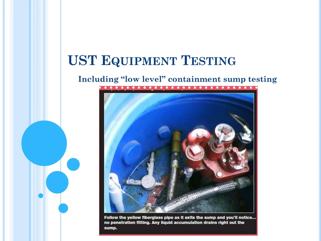
UST Equipment Testing Including “low level” containment sump testing
Any UST that is replaced or installed after November 26, 2009 must employ: • Secondary containment and approved continuous interstitial monitoring as a monthly leak detection method. • Must test all containment sumps at least once every three years to ensure liquid tightness using vacuum, pressure, or liquid testing unless the sump is double walled with periodic monthly monitoring • You must program the tank monitor to shutoff the dispenser and/or STP when liquid activates each sump sensor if you opt for new “low level” sump testing option.
Testing spill buckets and containment sumps • Last October MT DEQ revised containment sump testing regulations • Option 1: Spill prevention and containment sump equipment is double walled and the integrity of both walls is monitored at least as frequently as in the walkthrough inspection requirement (typically every 30 days for spill buckets, and annually for containment sumps). • If owners and operators discontinue this periodic monitoring, they have 30 days to conduct the test described in option 2 on next slide.
Testing spill buckets and containment sumps • Option 2: Spill buckets & all containment sumps used for interstitial monitoring of piping are tested at least once every 3 years. The test must determine that equipment is liquid tight by using either vacuum, pressure, or liquid testing according to one of the following: 1)Requirements developed by the manufacturer (owners and operators may only use this option if the manufacturer has developed testing requirements) 2)A code of practice developed by a nationally recognized association or independent testing laboratory 3)Requirements determined by the implementing agency to be no less protective than those developed by the manufacturer or in the code of practice
Into to PEI/RP 1200-17 • PR 1200-17 Purpose: • Protect human health and the environment • Promote safe and reliable operation of UST systems • Prevent spills and overfills associated with deliveries • Prevent damage to property and equipment
PEI RP 1200-17 - How to conduct testing of…. • Secondary Containment • Spill Prevention equipment • Overfill Equipment • Leak detection equipment • Shear Valves • Emergency Stops
Testing spill buckets and containment sumps • Spill prevention equipment and containment sumps used for interstitial monitoring of piping must be tested on or before October 13, 2021 for liquid tightness once every three years. Note that MT DEQ requires testing of this equipment for liquid tightness at installation – this will qualify as the first test. • DEQ recently added spill bucket liquid tightness testing to all spill bucket replacements
Spill Bucket & Containment Sump Testing • Spill Buckets- Test procedures for both single and double-walled spill buckets • Single-walled = Hydrostatic OR Vacuum Test • Double-walled = Vacuum test of interstice • Containment Sumps – Test procedure for single-walled containment sumps only • Single-walled = Hydrostatic Test
Spill Bucket & Containment Sump Testing • Single-Walled Spill Bucket – Hydrostatic Test • Clean and examine the spill bucket • Fill with water to within 1.5 inches of top • Measure water depth to nearest 1/16th inch • Monitor for 1 hour • Pass = Difference < 1/8 inch • Fail = Difference > or = to 1/8 inch
Spill Bucket & Containment Sump Testing • Single-Walled Spill Bucket- Hydrostatic Test • Be sure tank fill cap seals properly • Be sure drain valve seals properly • If these components don’t seal properly- water may enter the tank • Alternatively, you may temporarily install a plumbers plug in the fill riser and remove/plug the drain valve to ensure tight seals.
Spill Bucket & Containment Sump Testing • Single-Walled Spill Bucket- Vacuum Test • Clean and examine the spill bucket • Install special test cover • Pull a vacuum of 30 ’’ H2O Column • Monitor vacuum for 1 minute • Pass = Ending vacuum level > or = to 26 ’’ H20 column • Fail = Ending vacuum level < 26 inch H20 column • Note: This test does not generate any water
Spill Bucket & Containment Sump Testing • Double-Walled Spill Bucket- Vacuum Test • Clean and examine the spill bucket • Pull a vacuum of 15 ” H20 column on interstice • Monitor vacuum for 1 minute • Pass = Ending vacuum > or = to 12 ” H20 column • Fail = Ending vacuum < 12 ” H20 column
Spill Bucket & Containment Sump Testing • Double-Walled Spill Bucket- Vacuum Test • Testing the interstice of a double-walled spill bucket simultaneously test both the primary and secondary walls of the spill container.
Spill Bucket & Containment Sump Testing • Single-walled Containment sump- Hydrostatic Test • Clean, examine, and prepare the containment sump • Fill with water to 4” above the highest sump penetration • Measure water level to the nearest 1/16 inch • Monitor water level for 1 hour • Pass = Difference < 1/8 inch • Fail = Difference > or = to 1/8 inch
MT DEQ test requirements For Any UST Permit- Installations, repairs, and/or replacements • Hydrostatically test all containment sumps with liquid for one hour to a height 6 inches above the highest sump penetration. A passing test must show no liquid loss measured during the testing interval Must be: 6 inches above highest sump penetration!
Alternative “Low Level” Containment sump testing • Acceptable for compliance inspections with a written request from owner/operator/licensee. • Not acceptable for installs, modifications, repairs, etc.
Low Level sump testing procedure • A liquid sensor must be mounted at the lowest point in the sump. • Sumps must be free of debris and incidental moisture prior to testing. Remove any debris and any liquid in the sump prior to testing and visually check for cracks, holes, or compromised boots located in the portion of the sump where water will be added during testing. • Liquid/water is added into the sump until the liquid level is at least 4 inches above the height required to activate the sensor. Do not disturb the water in the sump for at least one hour. • Positive Shutdown Required: Only containment sumps with liquid sensors configured to shut down STP and/or dispenser upon activation of the sensor can qualify for this testing option. • Testing of sensor activation must be conducted annually according to the sensor manufacturer’s instructions for testing non-discriminating or discriminating sensors.
“low Level Containment sump testing • After one hour has elapsed if the level has dropped by more than 1/8 inch, then the sump failed the low liquid level hydrostatic integrity test. • Submit permit application within 30 days of failed test for repair or replacement. • Repaired or replaced sumps must pass 6” above highest penetration containment sump testing
Addressing Spill bucket/Sump testing Failures • Submit permit application to repair or replace spill container/containment sump within 30 days of testing fail • •For any repair or replacement even “Low Level” Containment Sump scenarios, sump must pass this test: Hydrostatically test all containment sumps with liquid for one hour to a height 6 inches above the highest sump penetration. A passing test must show no liquid loss measured during the testing interval
Overfill Prevention Inspection • Overfill prevention devices must be set to: Shutoff at 95 % tank capacity Restrict flow at 90 % tank capacity Alert the operator at 90 % tank capacity
Overfill Equipment Inspection & Testing • No later than October 13, 2021 : • owners and operators must have their overfill prevention equipment inspected for proper operation at least once every three years. Overfill prevention equipment installed or replaced after October 13, 2018 must be inspected for proper operation at installation and then once every three years.
Automatic Shutoff Devices (Flapper Valves) • Remove from the tank • Visually inspect (is float present?) • Manually operate valve to ensure it is functional • Measure length to ensure complete shutoff occurs when the tank is no more than 95 % full • Note: Ensure that complete shutoff point occurs at 95 % Flapper Valves:
Restriction Devices (Ball Float Valves) • Remove from the tank • Visually inspect • Measure length to ensure flow restriction occurs when the tank is no more than 90 % full • Note: All tank top fittings must be tight in order for the ball float valve to effectively restrict the flow. • If failed testing or replacing: Remove
Alert Devices (Electronic Alarms) HLA • Electronic Alarms typically part of the ATG system • Remove from the tank • Visually Inspect • Measure length to ensure that alarm occurs when the tank is no more than 90 % full • Note: Overfill alarms must provide an audible warning to the fuel delivery driver (outside! )
Electronic Monitoring System Inspection & Testing • Must be tested/inspected at least Annually! • Test/Inspection of the ATG system: • Console • In-tank probes • Interstitial sensors (tanks & piping) • Test is general in nature- Not intended as calibration of the ATG system
Electronic Monitoring System Inspection & testing • ATG Console: • Verify system is properly configured (setup) • Verify all site specific parameters are correct • Test the alarm • Test the battery backup • Verify that all indicator lamps function • Verify that printer functions • Verify that LCD display functions
Component Testing & Verification • ATG Probes: • Remove probe from tank • Visually inspect probe tank cap assembly • Visually inspect probe and floats • Verify that floats move freely • Verify all floats indicate the correct fluid levels and indicated fluid levels correspond with the programming (measured vs. ATG number)
Electronic Monitoring System Inspection & Testing • Interstitial Sensors: function test Annually • RP only considers sensors that function by detecting the presence of liquids (both discriminating and non-discriminating) • RP only considers float switch type sensors as these are the most common- • For other types of sensors – consult the manufacturer
Electronic Monitoring System Inspection • Interstitial Sensors: function test Annually • Verify that sensor is properly installed • Remove sensor from tank interstice or piping sump • Visually Inspect • Submerge sensor in appropriate test fluid (water for non-discriminating type) • Verify proper alarm condition and/or STP Shutdown • Verify sensor is properly labeled in ATG setup
Automatic Line Leak Detectors • Two Types of automatic line leak detectors • Function test Annually! • MechanicalElectronic
Automatic Line Leak Detectors • General: • Test procedures verify that the ALLD is capable of detecting a leak equivalent to 3.0 gph @ 10 psi • Test apparatus must have an adjustable orifice to properly simulate a leak equivalent to 3.0 gph @ 10 psi • Calibration of the adjustable orifice may be accomplished with or without the use of a pressure regulator LDT-890 Leak Detector Tester
Automatic Line Leak Detectors • General: • Test must confirm that the STP properly cycles on/off (verifies STP relays are functioning) • Simulated leak must occur at the dispenser that is at the highest elevation above the STP • If piping system has master/satellite configuration, simulated leak must occur at the farthest satellite dispenser
Automatic Line Leak Detectors • Mechanical Leak Detectors: • Visual inspection • Verify leak detector “trips” when line pressure nears zero • Verify leak detector “sees” a simulated leak equivalent to 3 gph @ 10 psi • “slow flow” conditions exists
Automatic Line Leak Detectors • Electronic Line Leak Detectors: • Function test Annually- NEW rule • Visual inspection • Verify system setup parameters are correct • Verify leak detector searches for leak • Verify leak detector sees simulated leak equivalent to 3 gph @ 10 psi • Causes alarm condition • Causes STP shutdown
Shear Valve Inspection & Testing • Product Shear Valves: • Visual Inspection • Verify anchored securely and at correct height • Confirm trip mechanism is functional • Manually close the valve poppet • Verify that no product flow occurs
Shear Valve Inspection & Testing • Pass/Fail Criteria: • Properly anchored to the dispenser box frame or dispenser island • Shear section located between ½ inch above and ½ below the level of the top surface of the dispenser island • Lever arm is free to rotate and able to snap the popet valve shut/closed • No fuel flow from the dispenser nozzle when the product shear valve is closed.
Emergency Stop Function testing • Manually activate switch to confirm power has been disconnected to: • All dispensers • All STPs • All power, control and signal circuits associated with dispensers and STPs • All other non-intrinsically safe electrical equipment in the classified areas of the UST system and dispensers