Download
1 / 27
270 likes | 439 Views
April 25, 2005. Introduction to SimCreator and Multi-Body Dynamics. What is SimCreator?. GUI Based System Modeling Package Similar to Simulink, SystemBuild, EASY5 Specialized for Realtime System Modeling: Driving Simulation, Flight Simulation, Games, Embedded Control

E N D
April 25, 2005 Introduction to SimCreator and Multi-Body Dynamics
What is SimCreator? • GUI Based System Modeling Package • Similar to Simulink, SystemBuild, EASY5 • Specialized for Realtime System Modeling: Driving Simulation, Flight Simulation, Games, Embedded Control • Modeling Constructs also Support Complex Off-Line Simulation
SimCreator Capabilities • Support for Single and Double Precision Models • Easy Editing of User Coded Components • Component Connectors Include a Description and Units • Vector Connections • Variable Width Components • Enhanced Metafile Based Icons • HTML Based Help Files • Sub Models
SimCreator Capabilities • Easy Access to and Setting of Initial Conditions • State Values Can be Overridden Inside User Code • Automatic C Code Generation • Multiprocessing with Multirate Integration • Generated C Code Uses Datafile Based Constants and Initial Conditions • Multiple Inputs and Outputs for User Coded Components • External Code Hooks to Inputs, Outputs, and Initial Conditions
SimCreator Capabilities • Highly Efficient Realtime Code • Mixed Continuous and Algebraic Inputs to Same User Code Block • Multiple Connections Can Be Made Between Components with a Single Mouse Click • Generates Embedded Code • Parallel and Distributed Build and Execution Environment • Highly Efficient Execution Interpretor
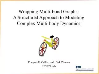
Multi-Body Dynamics • SimCreator’s multi-body dynamics component library is based on Composite Rigid Body Methods (CRBM) (recursive method) • CRBM method is used for open kinematic chains • For closed kinematic chains, constraint equations with corresponding Lagrange multipliers are introduced and are used to augment the mass matrix
Offset LinAccel1 LinAccel3 LinVel1 LinVel3 LinPos1 LinPos3 AngAccel1 AngAccel3 AngVel1 AngVel3 TM1 TM3 Force1 Force3 Moment1 Moment3 LinkNumber1 LinkNumber3 OffsetMB LocalJointAxis LinAccel1 LinAccel3 LinVel1 LinVel3 LinPos1 LinPos3 AngAccel1 AngAccel3 AngVel1 AngVel3 TM1 TM3 Force1 Force3 Moment1 Moment3 LinkNumber1 LinkNumber3 Revolute JointAng JointAngRate ExternalJointTorque Recursive Multi-Body Approach
Mass Matrix • To maintain real-time must select the appropriate joints to minimum the number of equations in the mass matrix
Double Pendulum Results • Z in SimCreator is–Y in DADS
Realtime Performance • The MTVR had the following complexity: • 66 equations in the augmented mass matrix • 36 equivalent joints • 25 equivalent bodies • 115 states • Full powertrain • 2nd order Runge-Kutta method at 500 Hz. • Using a computer with a 1.7 GHz Pentium M • MTVR model took 22 seconds to perform a 60 second simulation.
Powertrain • Vehicle subsystems are also broken down into reusable modules • Lowest level components are C code
SimCreator Conversion (Phase I SBIR) • DADS is a Cartesian multi-body modeling approach. Several steps are required to translate a Cartesian model into a recursive (CRBM) model, needed for real-time simulation in SimCreator. These steps include: • Determine weighting factors for each joint • Determine the best joints to cut • Determine the optimal base body • Build a recursive spanning tree • Minimize mass matrix size • Minimize tree length
Advantage Of GUI • Structured Framework to Build C Code Components • Causality • Unified Integration Algorithm • Built in Data Management and Plotting • Greater Insight Into the Model • Hierarchical Viewing • Model and Component Reuse