Download
1 / 77
800 likes | 1.1k Views
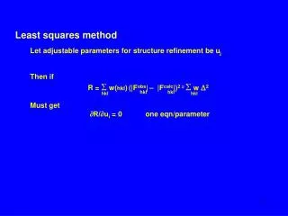
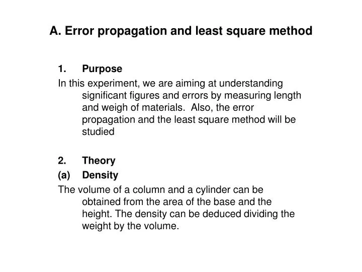
A. Error propagation and least square method. Purpose In this experiment, we are aiming at understanding significant figures and errors by measuring length and weigh of materials. Also, the error propagation and the least square method will be studied Theory Density

E N D
A. Error propagation and least square method Purpose In this experiment, we are aiming at understanding significant figures and errors by measuring length and weigh of materials. Also, the error propagation and the least square method will be studied Theory Density The volume of a column and a cylinder can be obtained from the area of the base and the height. The density can be deduced dividing the weight by the volume.
A. Error propagation and least square method Column the volume (V) and density (ρ) can be expressed as, Where D, L and M are diameter, height and weight of the column respectively
A. Error propagation and least square method Cylinder the area of the base is , where D and t are diameter and thickness of cylinder. The volume and the density are
A. Error propagation and least square method Error In principle, an experimental error can be reduced by repeating measurements. In this experiment, we repeat the measurement length and weight 5 times. The averaged value of measurements is adopted as the experimental results and the standard deviation is adopted as experimental errors of the volume and density ( ) can be described by the error propagation formula as,
A. Error propagation and least square method Column Cylinder Where δD, δL, δt and δM are the errors of each measurement
A. Error propagation and least square method Measurement A caliper, a scale, a calculator, a brass column and three brass cylinders with different size will be used in this experiment Column
A. Error propagation and least square method Measurement A caliper, a scale, a calculator, a brass column and three brass cylinders with different size will be used in this experiment Cylinder (1)
A. Error propagation and least square method Measurement A caliper, a scale, a calculator, a brass column and three brass cylinders with different size will be used in this experiment Cylinder (2)
A. Error propagation and least square method Measurement A caliper, a scale, a calculator, a brass column and three brass cylinders with different size will be used in this experiment Cylinder (3)
A. Error propagation and least square method Exercise 1. Calculate the average values of diameters, height and weight. The error size is determined from the standard deviation. Column
A. Error propagation and least square method Exercise 1. Calculate the average values of diameters, height and weight. The error size is determined from the standard deviation. Column
A. Error propagation and least square method Exercise 1. Calculate the average values of diameters, height and weight. The error size is determined from the standard deviation. Column
A. Error propagation and least square method Exercise 1. Calculate the average values of diameters, height, thickness and weight. The error size is determined from the standard deviation. Cylinder (1)
A. Error propagation and least square method Exercise 1. Calculate the average values of diameters, height, thickness and weight. The error size is determined from the standard deviation. Cylinder (1)
A. Error propagation and least square method Exercise 1. Calculate the average values of diameters, height, thickness and weight. The error size is determined from the standard deviation. Cylinder (1)
A. Error propagation and least square method Exercise 1. Calculate the average values of diameters, height, thickness and weight. The error size is determined from the standard deviation. Cylinder (1)
A. Error propagation and least square method Exercise 1. Calculate the average values of diameters, height, thickness and weight. The error size is determined from the standard deviation. Cylinder (2)
A. Error propagation and least square method Exercise 1. Calculate the average values of diameters, height, thickness and weight. The error size is determined from the standard deviation. Cylinder (2)
A. Error propagation and least square method Exercise 1. Calculate the average values of diameters, height, thickness and weight. The error size is determined from the standard deviation. Cylinder (2)
A. Error propagation and least square method Exercise 1. Calculate the average values of diameters, height, thickness and weight. The error size is determined from the standard deviation. Cylinder (2)
A. Error propagation and least square method Exercise 1. Calculate the average values of diameters, height, thickness and weight. The error size is determined from the standard deviation. Cylinder (3)
A. Error propagation and least square method Exercise 1. Calculate the average values of diameters, height, thickness and weight. The error size is determined from the standard deviation. Cylinder (3)
A. Error propagation and least square method Exercise 1. Calculate the average values of diameters, height, thickness and weight. The error size is determined from the standard deviation. Cylinder (3)
A. Error propagation and least square method Exercise 1. Calculate the average values of diameters, height, thickness and weight. The error size is determined from the standard deviation. Cylinder (3)
A. Error propagation and least square method Exercise 2. Calculate the volumes of all materials their errors. The error propagation procedure shown as Eq 1, 2 should be used for the error estimation. Column
A. Error propagation and least square method Exercise 2. Calculate the volumes of all materials their errors. The error propagation procedure shown as Eq 1, 2 should be used for the error estimation. Column
A. Error propagation and least square method Exercise 2. Calculate the volumes of all materials their errors. The error propagation procedure shown as Eq 1, 2 should be used for the error estimation. Cylinder (1)
A. Error propagation and least square method Exercise 2. Calculate the volumes of all materials their errors. The error propagation procedure shown as Eq 1, 2 should be used for the error estimation. Cylinder (1)
A. Error propagation and least square method Exercise 2. Calculate the volumes of all materials their errors. The error propagation procedure shown as Eq 1, 2 should be used for the error estimation. Cylinder (2)
A. Error propagation and least square method Exercise 2. Calculate the volumes of all materials their errors. The error propagation procedure shown as Eq 1, 2 should be used for the error estimation. Cylinder (2)
A. Error propagation and least square method Exercise 2. Calculate the volumes of all materials their errors. The error propagation procedure shown as Eq 1, 2 should be used for the error estimation. Cylinder (3)
A. Error propagation and least square method Exercise 2. Calculate the volumes of all materials their errors. The error propagation procedure shown as Eq 1, 2 should be used for the error estimation. Cylinder (3)
A. Error propagation and least square method Exercise 3. Plot the results in a graph. It is preferable that the volume is horizontal axis and the weight is vertical axis.
A. Error propagation and least square method Exercise 3. Plot the results in a graph. It is preferable that the volume is horizontal axis and the weight is vertical axis.
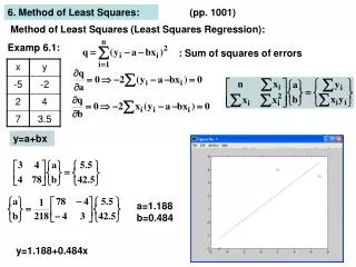
A. Error propagation and least square method Exercise 4. Determine the slope parameter (density) and its error by using the least square method.
A. Error propagation and least square method Exercise 4. Determine the slope parameter (density) and its error by using the least square method.
B. Measurement of damping motion using oscilloscope Purpose In this experiment, we are aiming at understanding operation mechanism and acquiring its basic handling. Damping motion is an electric circuit will be observe by the oscilloscope. Devices for this experiment 2.1 Oscilloscope An oscilloscope is to draw shape of electric signal on its display. Horizontal and vertical axes of the oscilloscope display are normally time and voltage.
B. Measurement of damping motion using oscilloscope 2.2 Pulsar A pulsar is device to generate AC signal. We can adjust signal shape (sine or rectangular waves). Set up - Oscilloscope: Kenwood CS-4125A Channel 1 - Pulsar: Kenwood AG-203D f = 12.5Hz Range x1K Amplitude (max) Waveform rectangular
B. Measurement of damping motion using oscilloscope 2.2 Pulsar A pulsar is device to generate AC signal. We can adjust signal shape (sine or rectangular waves). Set up - Oscilloscope: Kenwood CS-4125A Channel 1 - Pulsar: Kenwood AG-203D f = 12.5Hz Range x1K Amplitude (max) Waveform rectangular
B. Measurement of damping motion using oscilloscope 4. Damping motion Here we use an electric circuit composed of a condenser, a variable resistance and a coil. The electric signal from the pulsar is transmitted through the circuit and can be measure by the oscilloscope. We make the circuit the pulsar, the variable resistance and the condenser, as shown in the Fig. B2-2,3,4. During the discharge period, the electric motion can be described as,
B. Measurement of damping motion using oscilloscope Where Q charge of capacitor C, R* resistance of the system. Since Q = CV The time interval to the half of V0 is
B. Measurement of damping motion using oscilloscope We adjust variable resistance in order to get the time interval to half of V0. We have the results as shown below For C1
B. Measurement of damping motion using oscilloscope We adjust variable resistance in order to get the time interval to half of V0. We have the results as shown below For C2
B. Measurement of damping motion using oscilloscope We adjust variable resistance in order to get the time interval to half of V0. We have the results as shown below For C3
B. Measurement of damping motion using oscilloscope We plot the result as a function of R.
B. Measurement of damping motion using oscilloscope We plot the result as a function of R.
B. Measurement of damping motion using oscilloscope We plot the result as a function of R.
B. Measurement of damping motion using oscilloscope We determine r and C as an offset and a slope the graph, respectively which R* = R + r Where R is a variable resistance adjust variable and r is internal resistance r = 3.321 KΩ
B. Measurement of damping motion using oscilloscope Here we consider the electric circuit show in Fig. B2-2,3,4 as an application of above discussion. In addition to R and C, we will use a coil in this measurement. The derivative equation is Then taking into account I
B. Measurement of damping motion using oscilloscope Make the circuit shown in Fig. B2-8,9 and monitor the signal on the display of the oscilloscope (use 330pF capacitance and 102 coil). By changing R the transition from under-damping to over-damping through critical-damping which R = 2.23 KΩ. Determine the L value from R corresponding to the critical-damping by taking into account of ω = k. The derivative equation is Then taking into account ω