Download
1 / 25
1.17k likes | 2.69k Views
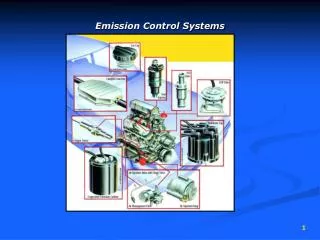
Emission Control System Fundamentals. Chapter 43. Objectives. Describe the different types of air pollution caused by motor vehicles Explain the fundamentals of the major emission control systems Label the parts of emission control systems

E N D
Emission Control System Fundamentals Chapter 43
Objectives • Describe the different types of air pollution caused by motor vehicles • Explain the fundamentals of the major emission control systems • Label the parts of emission control systems • Explain the operation of electronically controlled emission systems
Introduction • Emission controls • Began to be included on cars in the 1960s • Complicated specialty area • Most states: emission specialists are required to be licensed to perform repairs
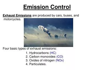
Air Pollution • Photochemical smog • Hydrocarbons and oxides of nitrogen react with sunlight • Warm air inversion layer traps smog • Pollution laws • Administered by the EPA • Vehicles manufactured today produce less than 5% of the air pollution of 1960s models
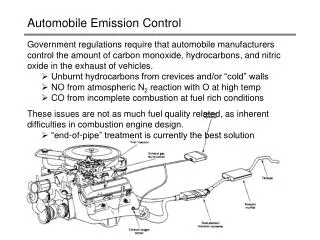
Automotive Emissions • Sources of emissions • Exhaust pipe, crank-case, and vapors • Hydrocarbon sources • Blowby gases • Skin effect • Raw gas in exhaust • Insufficient compression • Inadequate ignition spark
Automotive Emissions (cont'd.) • Carbon monoxide emissions • Result when gasoline not completely burned • Oxides of nitrogen • Produced when combustion temperatures are too high • Particulates • Are airborne microscopic particles • Carbon dioxide and oxygen • Used to diagnose combustion problems • Carbon dioxide is a greenhouse gas
Pollution Control • Early 1960s: California led emission control legislation • 1961: crankcase emission system required on all new cars in California • 1963: crankcase emission system required on all new cars in U.S. • 1966: exhaust emission systems required on new cars in California • 1970: U.S. Congress passed Clean Air Act
Automobile Emission Control Systems • Lower exhaust emissions • Engine design • Fuel and ignition system controls • Devices designed to control emissions • Computers manage emission devices • Engine load • Engine temperature • O2 sensor
Crankcase Ventilation • PCV system • Reintroduces blowby gases into combustion chambers • Benefits of PCV system • Prevents emissions of HCs • Reduces sludge • Reduces oil leakage • Closed ventilation system • Filtered intake air is supplied through hose from air cleaner
Air Injection System • Feeds hot gases to keep them burning • Air is provided by belt-driven air pump, electric motor-driven pump, or non-pump pulse air system • Functions • Provides low-pressure air supply • Provides air to catalytic converter • Air injection system uses an air pump, control valves, and lines to manifolds • Some vehicles have electric air pumps
Aspirator Valve or Pulse Air System • Momentary low-pressure condition (pulse) occurs at end of exhaust stroke • Aspirator valve or pulse air system uses pulses to blow fresh air into exhaust • Not efficient at high speeds • One-way check valve (i.e., aspirator valve) allows fresh air from cleaner • Flows when vacuum created by exhaust pulse • Closes when exhaust pressure builds
Exhaust Gas Recirculation • Lean air-fuel mixtures and higher operating temperatures raise NOX • Exhaust gas recirculation (EGR) system allows exhaust gas into air-fuel mixture • Diluting air-fuel mixture with exhaust gas lowers combustion temperature by 300°F • EGR improves fuel economy • Early EGR systems were often disabled to improve fuel economy
EGR System Operation • Simple EGR system has an EGR valve operated by engine vacuum • Located on intake manifold • Little NOX is formed at idle • EGR valve is closed at these times • Exhaust backpressure is a good indicator of engine load • More EGR flow needed under load • Thermal vacuum valve (TVV) • Prevents vacuum operation before engine is warm
Computer-Controlled EGR Systems • Today’s cars have computer-controlled EGR systems • EGR valve is controlled by input signals of engine temperature and load • Vehicle speed signal or PRNDL switch • Position sensors on EGR valves: included in late-model engines • Digital EGR valves: EGR flow regulated by computer using a series of solenoids • Linear EGR valves: include a stepper motor
Catalytic Converter • Catalyst • Causes chemical reaction without changing itself • Chemical reaction only occurs in presence of catalyst or occurs faster because of one • Catalytic converters • Must be hot to operate • Monolithic catalyst has thing coating of platinum applied to ceramic coated with alumina • Late-model vehicles have pre-catalysis which begin operating earlier
Types of Catalytic Converters • Two-way catalyst; changes HC and CO into CO2 and H2O • Three-way catalytic converter: used with oxygen sensor • Reduces NOX and oxidizes HC and CO • Single or dual bed design • Dual bed catalytic converters include air switching valve and diverter • Use rhodium as a catalyst • Needs heat and regulated air-fuel mixture
Evaporative Controls • Control emission of gasoline vapors from tank • Activated charcoal store gasoline vapors until they are drawn into the engine and burned • Emission of fuel vapors is controlled by sealing the fuel system • Gasoline tanks allow for fuel expansion of 10% • Expansion dome and liquid/vapor separator • Expansion tank • Filler neck design • Gas caps sealed or have pressure vacuum valve
Other Parts of the Fuel Tank System • Include: • Liquid vapor separator keeps liquid fuel from being drawn into charcoal canister • Charcoal canister stores vapors from fuel tank • Thermostatic air cleaner (TAC) maintain consistent air-fuel mixture • Manifold heat control valves were used to reduce exhaust emissions and improve drivability during engine warmup
On-Board Diagnostics • 1988: on-board diagnostics regulations became law • Require computer to monitor engine’s O2 sensor, EGR valve, and charcoal canister purge solenoid • Malfunction indicator light was also required • Names of emission parts and connections for test equipment were standardized • Part of the OBD II regulations
Engine Emission Modifications • Common modifications • As little as possible exposed surface area on the combustion chamber and top of piston • Engines run with higher cooling system temperatures • Advancing ignition timing can increase fuel economy • Changing cam design specifications results in different emissions • Domestic diesel light trucks and vans are now using urea selective catalyst reduction