Download
1 / 17
180 likes | 446 Views
Fault Injection in Mixed-Signal Environment Using Behavioral Fault Modeling in Verilog-A. Sharif University of Technology Department of Computer Engineering Dependable System Lab [DSL] . Seyed Nematollah Ahmadian , Seyed Ghassem Miremadi Behavioral Modeling and Simulation (BMAS) Conf.

E N D
Fault Injection in Mixed-Signal Environment Using Behavioral Fault Modeling in Verilog-A Sharif University of TechnologyDepartment of Computer Engineering Dependable System Lab [DSL] Seyed NematollahAhmadian, SeyedGhassemMiremadi Behavioral Modeling and Simulation (BMAS) Conf. September 2010
Outline • Dependability • Mixed Signal Flow • Behavioral Fault Modeling • Fault Models • Single Event Transient / Upset (SET/SEU) • Power Line Disturbance (PLD) • Electro Magnetic Interference (EMI) • Results
Dependability and Reliability • Dependability and Reliability • Not just words! • An effective technique for the experimental dependability evaluation • We propose a simulation-based fault injection method in mixed-signal environment.
Previous Fault Injection Tools • Level of abstraction Circuit HDL Too slow, too old. cannot include verification method like testbenches, etc. Does not include enough details For accurate modeling solution: Mixed-signal fault injection
Flow • Fault injection and simulation is performed in Mixed-Signal environment • Performance/Accuracy tradeoff • More accurate than RTL simulation • Faster than SPICE simulation • Fault injection on SoCs with analog cores • PLLs, DLLs, SRAMs, …
Flow • SPICE simulation near the fault site: • accurate fault simulation • HDL Simulation (elsewhere) • Motive: Most of the fault manifest themselves as and error outside the fault site • HDL simulation provides enough accuracy to continue simulation. • Original testbenches/verification scripts are intact • Faster simulation. Can compensate for the SPICE simulation penalty.
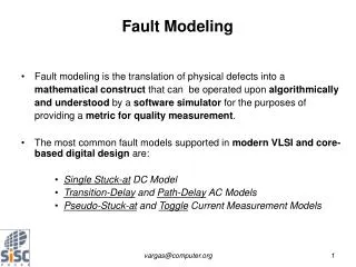
Fault Modeling • We develop fault models in behavioral modeling languages (such as Verilog-A) • Easy modeling • Reduce development time • Accurate simulations • Access to internal nodes/ structure of transistor/electrical element
Tool-chain architecture • Mixed-signal three-level of abstraction • Faults are embedded inside Verilog-A model. • Resulted fault models are inserted to Circuit as an external component
Fault models • Behavioral fault modeling • Single Event Transients/Upset (SET/SEU) • Electro-Magnetic Interference (EMI) • Power Line Disturbance (PLD) • Our flow supports other fault models as well.
SET Fault Modeling • Cause: hitting a high-power particle into transistors diffusion area. • Effect: transient current spike on diffusion, single event transient and upset.
Electro-Magnetic Interference Modeling • EM or RF induced interference • Modeled as a Continues-wave RFI superimposed on specific nodes. • Input • Clock • …
Power Line Disturbance Modeling • Common PLDs: • Power supply noise • Overshoot, Undershoot • Ground Bouncing
Experimental Setup • We used the following 3rd party tools and IPs: • HDL Simulator: ModelSim 6.5 SE • Spice Simulator: Synopsys HSIM 2008.09 • Process: TSMC 0.25μm • Our fault characteristics: • SET: Q=10pc, with TO=TB=10ns , Random injection, Two exponential model • EMI: 100 MHz CW RF signal, Vpeak= 0.5V , 100ns pulse envelope, Random injection • PLD: 100ns duration, Voltage shortage (from 2.5V to 0V ) on VDD line, Random injection
Thank you! • Questions? • Thank you for your attention.