Download
1 / 15
150 likes | 285 Views
35. Tires and Wheels. FIGURE 35.1 (a) A typical tire tread depth gauge. The center movable plunger is pushed down into the groove of the tire. (b) The tread depth is read at the top edge of the sleeve. In this example, the tread depth is 6/32 in.

E N D
35 Tires and Wheels
FIGURE 35.1 (a) A typical tire tread depth gauge. The center movable plunger is pushed down into the groove of the tire. (b) The tread depth is read at the top edge of the sleeve. In this example, the tread depth is 6/32 in.
FIGURE 35.2 Wear indicators (wear bars) are strips of bald tread that show when the tread depth is down to 2/32 in., the legal limit in many states.
FIGURE 35.3 Hydroplaning can occur at speeds as low as 30 mph (48 km/h). If the water is deep enough and the tire tread cannot evacuate water through its grooves fast enough, the tire can be lifted off the road surface by a layer of water. Hydroplaning occurs at lower speeds as the tire becomes worn.
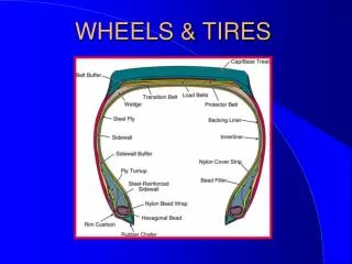
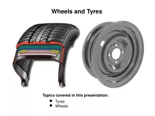
FIGURE 35.4 Typical construction of a radial tire. Some tires have only one body ply, and some tires use more than two belt plies.
FIGURE 35.5 The major splice of a tire can often be seen and felt on the inside of the tire. The person who assembles (builds) the tire usually places a sticker near the major splice as a means of identification for quality control.
FIGURE 35.6 Typical “Uniform Tire Quality Grading System” (UTQGS) ratings imprinted on the tire sidewall.
FIGURE 35.7 The wheel rim well provides a space for the tire to fit during mounting; the bead seat provides a tire-to-wheel sealing surface; the flange holds the beads in place.
FIGURE 35.8 A typical JWL symbol for the Japan Wheel Light Metal standard mark.
FIGURE 35.9 (a) A rubber snap-in–style tire valve assembly. (b) A metal clamp–type tire valve assembly used on most high pressure (over 60 PSI) tire applications such as is found on many trucks, RVs, and trailers. The internal Schrader valve threads into the valve itself and can be replaced individually, but most experts recommend replacing the entire valve assembly every time the tires are replaced to help prevent air loss.
FIGURE 35.11 The tire pressure placard (sticker) on the driver’s side door or door jamb indicates the specified tirepressure. The specified inflation pressure is when the tires are cold and the vehicle has not been driven for several hours.
FIGURE 35.12 The method most often recommended is the modified X method. Using this method, each tire eventually is used at each of the four wheel locations. An easy way to remember the sequence, whether front-wheel drive or rear-wheel drive, is to say to yourself, “Drive wheels straight, cross the nondrive wheels.”
FIGURE 35.13 A torque-limiting adapter (torque stick) for use with an air impact wrench still requires care to prevent over tightening. The air pressure to the air impact should be limited to 125 PSI (860 kPa) in most cases, and the proper adapter must be selected for the vehicle being serviced. The torque adapter absorbs any torque beyond its designed rating. Most adapters are color coded for easy identification as to the size of lug nut and torque value.
FIGURE 35.14 Always tighten wheel lug nuts (or studs) in a star pattern to ensure even pressure on the axle flange, brake rotors or drums, and the wheel itself.