Download
1 / 35
360 likes | 610 Views
Interfacing. Outline. Interfacing basics Microprocessor interfacing I/O Addressing Interrupts Direct memory access Arbitration Hierarchical buses Protocols Serial Parallel Wireless. Introduction. Embedded system functionality aspects Processing Transformation of data

E N D
Outline • Interfacing basics • Microprocessor interfacing • I/O Addressing • Interrupts • Direct memory access • Arbitration • Hierarchical buses • Protocols • Serial • Parallel • Wireless
Introduction • Embedded system functionality aspects • Processing • Transformation of data • Implemented using processors • Storage • Retention of data • Implemented using memory • Communication • Transfer of data between processors and memories • Implemented using buses • Called interfacing
rd'/wr Processor Memory enable addr[0-11] data[0-7] bus bus structure A simple bus • Wires: • Uni-directional or bi-directional • One line may represent multiple wires • Bus • Set of wires with a single function • Address bus, data bus • Or, entire collection of wires • Address, data and control • Associated protocol: rules for communication
rd'/wr Processor Memory port enable addr[0-11] data[0-7] Ports • Conducting device on periphery • Connects bus to processor or memory • Often referred to as a pin • Actual pins on periphery of IC package that plug into socket on printed-circuit board • Sometimes metallic balls instead of pins • Today, metal “pads” connecting processors and memories within single IC • Single wire or set of wires with single function • E.g., 12-wire address port bus
rd'/wr enable addr data tsetup tread read protocol rd'/wr enable addr data tsetup twrite write protocol Timing Diagrams • Most common method for describing a communication protocol • Time proceeds to the right on x-axis • Control signal: low or high • May be active low (e.g., go’, /go, or go_L) • Use terms assert (active) and deassert • Asserting go’ means go=0 • Data signal: not valid or valid • Protocol may have subprotocols • Called bus cycle, e.g., read and write • Each may be several clock cycles • Read example • rd’/wr set low,address placed on addr for at least tsetup time before enable asserted, enable triggers memory to place data on data wires by time tread
Time-multiplexed data transfer Master Servant Master Servant req req 7:0 15:8 data(15:0) data(15:0) addr data addr data mux demux mux demux data(8) addr/data req req data addr/data data serializing address/data muxing addr data Basic protocol concepts • Actor: master initiates, servant (slave) respond • Direction: sender, receiver • Addresses: special kind of data • Specifies a location in memory, a peripheral, or a register within a peripheral • Time multiplexing • Share a single set of wires for multiple pieces of data • Saves wires at expense of time
Master Servant Master req Servant req ack data data req 1 3 req 1 3 ack 2 4 data 2 4 data taccess 1. Master asserts req to receive data 1. Master asserts req to receive data 2. Servant puts data on bus within time taccess 2. Servant puts data on bus and asserts ack 3. Master receives data and deasserts req 3. Master receives data and deasserts req 4. Servant ready for next request 4. Servant ready for next request Strobe protocol Handshake protocol Basic protocol concepts: control methods
Microprocessor interfacing: I/O addressing • A microprocessor communicates with other devices using some of its pins • Port-based I/O (parallel I/O) • Processor has one or more N-bit ports • Processor’s software reads and writes a port just like a register • E.g., P0 = 0xFF; v = P1.2; -- P0 and P1 are 8-bit ports • Bus-based I/O • Processor has address, data and control ports that form a single bus • Communication protocol is built into the processor • A single instruction carries out the read or write protocol on the bus
Processor Memory Processor Port 0 Port 1 Port 2 System bus Port 3 Parallel I/O peripheral Parallel I/O peripheral Port A Port B Port C Port A Port B Port C Adding parallel I/O to a bus-based I/O processor Extended parallel I/O Compromises/extensions • Parallel I/O peripheral • When processor only supports bus-based I/O but parallel I/O needed • Each port on peripheral connected to a register within peripheral that is read/written by the processor • Extended parallel I/O • When processor supports port-based I/O but more ports needed • One or more processor ports interface with parallel I/O peripheral extending total number of ports available for I/O • e.g., extending 4 ports to 6 ports in figure
Types of bus-based I/O: memory-mapped I/O and standard I/O • Processor talks to both memory and peripherals using same bus – two ways to talk to peripherals • Memory-mapped I/O • Peripheral registers occupy addresses in same address space as memory • e.g., Bus has 16-bit address • lower 32K addresses may correspond to memory • upper 32k addresses may correspond to peripherals • Standard I/O (I/O-mapped I/O) • Additional pin (M/IO) on bus indicates whether a memory or peripheral access • e.g., Bus has 16-bit address • all 64K addresses correspond to memory when M/IO set to 0 • all 64K addresses correspond to peripherals when M/IO set to 1
Memory-mapped I/O vs. Standard I/O • Memory-mapped I/O • Requires no special instructions • Assembly instructions involving memory like MOV and ADD work with peripherals as well • Standard I/O requires special instructions (e.g., IN, OUT) to move data between peripheral registers and memory • Standard I/O • No loss of memory addresses to peripherals • Simpler address decoding logic in peripherals possible • When number of peripherals much smaller than address space then high-order address bits can be ignored • smaller and/or faster comparators
ISA I/O bus read protocol C1 C2 WAIT C3 C4 CYCLE CLOCK D[7-0] A[15-0] ALE /IOR CHRDY DATA ADDRESS ISA bus • ISA supports standard I/O • /IOR distinct from /MEMR for peripheral read • /IOW used for writes • 16-bit address space for I/O vs. 20-bit address space for memory • Otherwise very similar to memory protocol
Microprocessor interfacing: interrupts • Suppose a peripheral intermittently receives data, which must be serviced by the processor • The processor can poll the peripheral regularly to see if data has arrived – wasteful • The peripheral can interrupt the processor when it has data • Requires an extra pin or pins: Int • If Int is 1, processor suspends current program, jumps to an Interrupt Service Routine, or ISR • Known as interrupt-driven I/O • Essentially, “polling” of the interrupt pin is built-into the hardware, so no extra time!
Microprocessor interfacing: interrupts • What is the address (interrupt address vector) of the ISR? • Fixed interrupt • Address built into microprocessor, cannot be changed • Either ISR stored at address or a jump to actual ISR stored if not enough bytes available • Vectored interrupt • Peripheral must provide the address • Common when microprocessor has multiple peripherals connected by a system bus • Compromise: interrupt address table
Direct memory access • Buffering • Temporarily storing data in memory before processing • Data accumulated in peripherals commonly buffered • Microprocessor could handle this with ISR • Storing and restoring microprocessor state inefficient • Regular program must wait • DMA controller more efficient • Separate single-purpose processor • Microprocessor relinquishes control of system bus to DMA controller • Microprocessor can meanwhile execute its regular program • No inefficient storing and restoring state due to ISR call • Regular program need not wait unless it requires the system bus • Harvard archictecture – processor can fetch and execute instructions as long as they don’t access data memory – if they do, processor stalls
Intel 8237 REQ 0 ACK 0 REQ 1 ACK 1 REQ 2 ACK 2 REQ 3 ACK 3 D[7..0] A[19..0] ALE MEMR MEMW IOR IOW HLDA HRQ Intel 8237 DMA controller
Intel 8259 IR0 IR1 IR2 IR3 IR4 IR5 IR6 IR7 D[7..0] A[0..0] RD WR INT INTA CAS[2..0] SP/EN Intel 8259 programmable priority controller
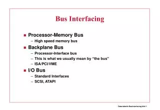
Micro- processor Cache Memory controller DMA controller Processor-local bus Peripheral Peripheral Peripheral Bridge Peripheral bus Multilevel bus architectures • Don’t want one bus for all communication • Peripherals would need high-speed, processor-specific bus interface • excess gates, power consumption, and cost; less portable • Too many peripherals slows down bus • Processor-local bus • High speed, wide, most frequent communication • Connects microprocessor, cache, memory controllers, etc. • Peripheral bus • Lower speed, narrower, less frequent communication • Typically industry standard bus (ISA, PCI) for portability • Bridge • Single-purpose processor converts communication between busses
Advanced communication principles • Layering • Break complexity of communication protocol into pieces easier to design and understand • Lower levels provide services to higher level • Lower level might work with bits while higher level might work with packets of data • Physical layer • Lowest level in hierarchy • Medium to carry data from one actor (device or node) to another • Parallel communication • Physical layer capable of transporting multiple bits of data • Serial communication • Physical layer transports one bit of data at a time • Wireless communication • No physical connection needed for transport at physical layer
Parallel communication • Multiple data, control, and possibly power wires • One bit per wire • High data throughput with short distances • Typically used when connecting devices on same IC or same circuit board • Bus must be kept short • long parallel wires result in high capacitance values which requires more time to charge/discharge • Data misalignment between wires increases as length increases • Higher cost, bulky
Serial communication • Single data wire, possibly also control and power wires • Words transmitted one bit at a time • Higher data throughput with long distances • Less average capacitance, so more bits per unit of time • Cheaper, less bulky • More complex interfacing logic and communication protocol • Sender needs to decompose word into bits • Receiver needs to recompose bits into word • Control signals often sent on same wire as data increasing protocol complexity
Wireless communication • Infrared (IR) • Electronic wave frequencies just below visible light spectrum • Diode emits infrared light to generate signal • Infrared transistor detects signal, conducts when exposed to infrared light • Cheap to build • Needline of sight, limited range • Radio frequency (RF) • Electromagnetic wave frequencies in radio spectrum • Analog circuitry and antenna needed on both sides of transmission • Line of sight not needed, transmitter power determines range
Error detection and correction • Often part of bus protocol • Error detection: ability of receiver to detect errors during transmission • Error correction: ability of receiver and transmitter to cooperate to correct problem • Typically done by acknowledgement/retransmission protocol • Bit error: single bit is inverted • Burst of bit error: consecutive bits received incorrectly • Parity: extra bit sent with word used for error detection • Odd parity: data word plus parity bit contains odd number of 1’s • Even parity: data word plus parity bit contains even number of 1’s • Always detects single bit errors, but not all burst bit errors • Checksum: extra word sent with data packet of multiple words • e.g., extra word contains XOR sum of all data words in packet
Serial protocols: I2C • I2C (Inter-IC) • Two-wire serial bus protocol developed by Philips Semiconductors nearly 20 years ago • Enables peripheral ICs to communicate using simple communication hardware • Data transfer rates up to 100 kbits/s and 7-bit addressing possible in normal mode • 3.4 Mbits/s and 10-bit addressing in fast-mode • Common devices capable of interfacing to I2C bus: • EPROMS, Flash, and some RAM memory, real-time clocks, watchdog timers, and microcontrollers
SCL SDA SDA SDA SDA SDA Start condition Sending 0 Sending 1 Stop condition SCL SCL SCL SCL Micro-controller (master) EEPROM (servant) LCD-controller (servant) Temp. Sensor (servant) From receiver From Servant D < 400 pF C ST ART A6 A5 A0 R/w ACK D8 D7 D0 ACK ST OP Addr=0x01 Addr=0x02 Addr=0x03 Typical read/write cycle I2C bus structure
Serial protocols: CAN • CAN (Controller area network) • Protocol for real-time applications • Developed by Robert Bosch GmbH • Originally for communication among components of cars • Applications now using CAN include: • elevator controllers, copiers, telescopes, production-line control systems, and medical instruments • Data transfer rates up to 1 Mbit/s and 11-bit addressing • Common devices interfacing with CAN: • 8051-compatible 8592 processor and standalone CAN controllers • Actual physical design of CAN bus not specified in protocol • Requires devices to transmit/detect dominant and recessive signals to/from bus • e.g., ‘1’ = dominant, ‘0’ = recessive if single data wire used • Bus guarantees dominant signal prevails over recessive signal if asserted simultaneously
Serial protocols: FireWire • FireWire (a.k.a. I-Link, Lynx, IEEE 1394) • High-performance serial bus developed by Apple Computer Inc. • Designed for interfacing independent electronic components • e.g., Desktop, scanner • Data transfer rates from 12.5 to 400 Mbits/s, 64-bit addressing • Plug-and-play capabilities • Packet-based layered design structure • Applications using FireWire include: • disk drives, printers, scanners, cameras • Capable of supporting a LAN similar to Ethernet • 64-bit address: • 10 bits for network ids, 1023 subnetworks • 6 bits for node ids, each subnetwork can have 63 nodes • 48 bits for memory address, each node can have281 terabytesof distinctlocations
Serial protocols: USB • USB (Universal Serial Bus) • Easier connection between PC and monitors, printers, digital speakers, modems, scanners, digital cameras, joysticks, multimedia game equipment • 2 data rates: • 12 Mbps for increased bandwidth devices • 1.5 Mbps for lower-speed devices (joysticks, game pads) • Tiered star topology can be used • One USB device (hub) connected to PC • hub can be embedded in devices like monitor, printer, or keyboard or can be standalone • Multiple USB devices can be connected to hub • Up to 127 devices can be connected like this • USB host controller • Manages and controls bandwidth and driver software required by each peripheral • Dynamically allocates power downstream according to devices connected/disconnected
Parallel protocols: PCI Bus • PCI Bus (Peripheral Component Interconnect) • High performance bus originated at Intel in the early 1990’s • Standard adopted by industry and administered by PCISIG (PCI Special Interest Group) • Interconnects chips, expansion boards, processor memory subsystems • Data transfer rates of 127.2 to 508.6 Mbits/s and 32-bit addressing • Later extended to 64-bit while maintaining compatibility with 32-bit schemes • Synchronous bus architecture • Multiplexed data/address lines
Parallel protocols: ARM Bus • ARM Bus • Designed and used internally by ARM Corporation • Interfaces with ARM line of processors • Many IC design companies have own bus protocol • Data transfer rate is a function of clock speed • If clock speed of bus is X, transfer rate = 16 x X bits/s • 32-bit addressing
Wireless protocols: IrDA • IrDA • Protocol suite that supports short-range point-to-point infrared data transmission • Created and promoted by the Infrared Data Association (IrDA) • Data transfer rate of 9.6 kbps and 4 Mbps • IrDA hardware deployed in notebook computers, printers, PDAs, digital cameras, public phones, cell phones • Lack of suitable drivers has slowed use by applications • Windows 2000/98 now include support • Becoming available on popular embedded OS’s
Wireless protocols: Bluetooth • Bluetooth • New, global standard for wireless connectivity • Based on low-cost, short-range radio link • Connection established when within 10 meters of each other • No line-of-sight required • e.g., Connect to printer in another room
Wireless Protocols: IEEE 802.11 • IEEE 802.11 • Proposed standard for wireless LANs • Specifies parameters for PHY and MAC layers of network • PHY layer • physical layer • handles transmission of data between nodes • provisions for data transfer rates of 1 or 2 Mbps • operates in 2.4 to 2.4835 GHz frequency band (RF) • or 300 to 428,000 GHz (IR) • MAC layer • medium access control layer • protocol responsible for maintaining order in shared medium • collision avoidance/detection
Summary • Basic protocol concepts • Actors, direction, time multiplexing, control methods • General-purpose processors • Port-based or bus-based I/O • I/O addressing: Memory mapped I/O or Standard I/O • Direct memory access • Bus hierarchy • Advanced communication • Parallel vs. serial, wires vs. wireless, error detection/correction, layering • Serial protocols: I2C, CAN, FireWire, and USB; Parallel: PCI and ARM. • Serial wireless protocols: IrDA, Bluetooth, and IEEE 802.11.