Download
1 / 31
310 likes | 399 Views
Prototype Earth observing System using Image Slicer Mirrors PERSIST . David Lee, Andy Vick, Peter Hastings, David Atkinson, Martin Black and Sandi Wilson STFC, UK Astronomy Technology Centre James Barlow and Paul Palmer Department of GeoSciences , University of Edinburgh.

E N D
Prototype Earth observing System using Image Slicer MirrorsPERSIST David Lee, Andy Vick, Peter Hastings, David Atkinson, Martin Black and Sandi Wilson STFC, UK Astronomy Technology Centre James Barlow and Paul Palmer Department of GeoSciences, University of Edinburgh
Presentation overview • Introduction & Background • PERSIST concept • Description of PERSIST hardware • PERSIST test results • GHOST • Summary & Conclusions
Hyperspectral Imaging • Measurement of the concentration of atmospheric gases, such as Carbon Dioxide or Methane, is often performed using a hyperspectral imager. • Hyperspectral imagers typically use two technologies: • Push-broom spectrometers. • Fourier transform spectrometers.
Push-Broom Spectrometers • Push-broom spectrometers use satellite motion to scan a single slit across the scene. • Observation of multiple wavelength channels requires multiple spectrometers and multiple detectors. • Increased observing efficiency can be obtained by simultaneously observing multiple channels with one spectrometer.
Layout of a Typical Push-Broom Spectrometer • Single input slit and relay optics to sort light into three channels, e.g. O2 A-band, CO2 (weak), CO2 (strong). • 3 spectrometers and 3 detectors.
Layout of PERSIST • Input field of view is 3 slits. • Image slicer mirror optical system relays the light to the spectrometer. • Band-pass filters are used to define three wavelength channels. • Multiple order spectrometer simultaneously observes all wavelength channels.
PERSIST operational concept • Push-Broom spectrometer with along track scanning. • Multiple slits sample the field of view. • Spectrometer operates with multiple diffraction orders to simultaneously observe 3 wavelengths of interest. • Alternatively can observe same scene 3 times to obtain a higher signal.
JWST MIRI heritage • James Webb Space Telescope has two instruments with image slicer technology • MIRI – image slicers designed at UK ATC • NIRSPEC (Astrium) James Webb Space Telescope MIRI Image Slicer Mirror with 21 slices MIRI at STFC RAL Space
PERSIST objectives • The purpose of the PERSIST project is to build a bench mounted prototype image slicer spectrometer with a SWIR detector system. • The system will demonstrate the ability to simultaneously capture three wavelength ranges (via three slices) on one detector. • The prototype will demonstrate the feasibility of the technology for use in an Earth Observation instrument to measure atmospheric CO2. • Increase TRL of multiple-order spectrometer.
Optical layout of PERSIST IFU Entrance Aperture Fold Mirror Reimaging Lenses Image Slicer Collimator Bandpass Filters Slits Zemax optical ray trace diagram
PERSIST Image Slicer • Diamond machined aluminium. • Off-axis spherical slices. • Component includes input aperture. • Area surrounding slice will have a black mask.
Integral Field Module Integral-Field Module external view 195 mm 40 mm square
Integral Field Module with Image Slicer entrance aperture Integral-Field Module cross-section of hardware slicing mirror mirror unit central housing fold mirror lens unit collimating lens field-imaging lens order-sorting filter pupil-imaging lens slit mask
Integral Field module hardware IFU housing components Pupil baffle Masks Spacer tubes Output Slit Filters Image Slicer Fold Mirror Collimator Lens Re-imaging Lenses Pupil Lenses
Fully Assembled IFU module Fold Mirror Image Slicer Lens Barrel Output Slit White Light Input Output three pass bands 150 mm
Layout of output slit Picture of IFU output slit showing the three wavelength channels Reverse illumination to demonstrate field of view
Layout of bench spectrometer • Simple bench spectrometer using COTS components • Operates in diffraction orders 8, 5, 4. • Raytheon VIRGO SWIR detector. Fold Mirror Grating Camera Collimator Input Slit Window Blocking Filter Bandpass Filter Detector Zemax optical ray trace diagram
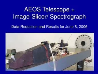
PERSIST – Fully Assembled Monochromator Telescope Simulator IFU module Detector Collimator Lens Diffraction Grating
PERSIST – Layout on Bench Monochromator Light Source IFU Telescope Simulator Cryostat Cooling System
Integration and Test • A wavelength scan was performed with the monochromator to look for out of band stray light. • Arc Lamp illumination to perform image quality checks from spectral line width. • IFU illuminated with white light via an integrating sphere to generate three spectra. Check area between spectra for scattered light. • Measurement of atmospheric spectrum.
Illumination with Monochromatic Light Full frame image at 1600 nm Enlarged view of the spectrum showing the spatial structure of the lamp filament
Simultaneous Capture of Three Spectral Bands Illumination with a Filament Lamp Uniform Illumination 1600 nm 1020 nm 2000 nm
Measurement of Scattered Light Contrast enhanced image showing scattered light between spectra Plot of intensity along a column, scattered light level is < 2 % of peak intensity
Example atmospheric spectrum Test set-up Plot of 1020 nm spectrum • Small telescope located outside lab • Telescope pointed directly at sun • Optical fibre feed to PERSIST • Spectrum formed shown below
Technology Highlights • The imager slicer technology provides a compact design that may benefit future instruments. • Overall PERSIST performs well – low level of scattered light and no light leaks. • Technology applicable to a variety of wavelengths simply by changing the filters. • High resolution multiple order spectrometer is being built for GHOST
GHOST • GHOST – Green House Observations of the Stratosphere and Troposphere. • Multiple order SWIR spectrometer is being built for use on a NASA global hawk UAV. • High resolution SWIR hyper-spectral imager for CO2 and CH4 measurement.
Summary & Conclusions • PERSIST has demonstrated the feasibility of using image slicers and multiple order spectrometers for remote sensing. • Performance gains are possible compared with conventional push-broom systems. • Enables construction of smaller instruments. • Technology is well suited to observation of modest swath widths and 3 – 5 wavelength channels, e.g. atmospheric CO2and CH4 observation.
Contact Information • David Lee • david.lee@stfc.ac.uk • Science & Technology Facilities Council • www.stfc.ac.uk • www.atcinnovations.com • Centre for Earth Observation Instrumentation • www.ceoi.ac.uk
PERSIST End of presentation