Download
1 / 30
300 likes | 397 Views
Gamma-ray Large Area Space Telescope. Data Acquisition System Issues for Large Experiments Semiconductor Tracking Detector “Hiroshima” Symposium 6 Eric J. Siskind SLAC/NYCB Real-Time Computing, Inc. ejs@slac.stanford.edu (516) 759-0707. Introduction.

E N D
Gamma-ray Large Area Space Telescope Data Acquisition System Issues for Large Experiments Semiconductor Tracking Detector “Hiroshima” Symposium 6 Eric J. Siskind SLAC/NYCB Real-Time Computing, Inc. ejs@slac.stanford.edu (516) 759-0707
Introduction • All highly personal opinion – not authoritative. • First part: lessons learned from GLAST LAT DAQ system. • Did NOT work on overall DAQ system design. • Did NOT work on TKR front-end electronics. • Did implement & debug second and third tier of DAQ. • Did implement & debug front-end electronics simulator. • Did contribute to overall system debug. • Acquired expertise on other portions through curiosity. • Second part: features and pitfalls of “System FPGAs” – FPGAs with hard PowerPC processor cores integrated into fixed locations in the die. Eric J. Siskind, September 14, 2006
LAT TKR DAQ Architecture • Detector has 864k Silicon strips total. • 16 towers. • 36 layers (18 X, 18 Y) per tower; front-end electronics for 9 layers on each of 4 sides. • 1,536 Si strips per layer. • Pipeline consists of on-detector front-end electronics plus three tiers of DAQ boxes. • Last tier is “level-3 processor farm” of 3 nodes (2 active plus 1 cold spare). • 5 tiers of hardware buffer prior to 512 kB circular buffer in main memory of each farm processor – 2 in front-end electronics plus 1 in each DAQ tier. Eric J. Siskind, September 14, 2006
Electronics Overview • Three types of ASIC – multiplicities of 13.5k (GTFE), 1,152 (GTRC), and 128 (GTCC). • Five types of FPGA – multiplicities of 16, 2 (1+1), 1, and 2 types at 1 per processor. All in Actel RTSX72SU • (Overall LAT – 9 types of ASIC; 12/3 types of Actel RTSX72/32SU FPGA.) Eric J. Siskind, September 14, 2006
Front-End Electronics (Multichip Modules) • 24 GTFE front-end ASICs per layer; 64 channels of preamp & discriminator each. • MCM is dual daisy chain (left right, right left) with GTRC readout controller ASIC at each end. Nominal split is 12/12 GTFEs reading out to left/right. • Readout cable at each end of each tower side daisy-chained through 9 GTRCs. • Four 64-bit raw data buffers per GTFE. • Two 64-hit buffers per GTRC holding 11-bit zero-suppressed hit strip addresses. GTRCs GTFEs MCMs Eric J. Siskind, September 14, 2006
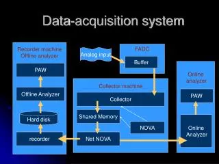
TKR DAQ Pipeline Overview Front Ends (576 MCMs) 1st DAQ Tier 2nd DAQ Tier 3rd DAQ Tier TEM EPU Level-3 Trigger TEM GASU GTFEs (X13.5k) GTRCs (X1,152) EPU TEM FRONT-END READOUT CABLES (X128) (X16) SPACECRAFT SOLID-STATE RECORDER Eric J. Siskind, September 14, 2006
Tower Electronics Module Engineering Model TEM before coating/staking • First-tier DAQ module – one per tower. • Contains 8 GTCC cable controller ASICs – one per front-end readout cable. • Single 128-entry by 16-bit FIFO per GTCC for zero-suppressed hits; 11 bits of hit strip address from GTRC plus end-of-layer bit; 4 bits unused. • GTIU common controller FPGA reads GTCC FIFOs over 16-bit TEM-wide 3-state bus; constructs TEM event contribution, serializes, and ships to event builder. • Output event data in 128-bit LATp cells; 12 bits per hit strip in GTCC FIFO 11+1 format. GTCC Cable Controller ASICs GTIU Common Controller FPGA Eric J. Siskind, September 14, 2006
Event Builder in Global Electronics Unit Engineering Model GASU • Duplicate boards contain EBM event builder, global trigger, command/clock/reset fan-out & response fan-in, and anti-coincidence detector electronics interface. • Data from 8 TEMs serviced by each EBM input FPGA; deserializes incoming event data stream and stores in 512k x 32 SRAM for each FPGA. • Separate 8 kB circular buffer region in SRAM for data stream from each TEM – operates as an effective data FIFO. • EBM input FPGA sends data from SRAM circular buffers as a byte stream to the output FPGA, which forwards the stream to target level-3 trigger computer (EPU). Power Supply DAQ Board Primary EBM FPGAs GASU Assembly Eric J. Siskind, September 14, 2006
cPCI PowerPC Computer Crate • LCB LAT Communications Board provides cPCI DMA interface between RAD750 processor board main memory and GASU. • LCB LAT FPGA receives event data byte stream from EBM, deserializes into 32-bit words, and stores these data in a discrete 1k x 32 FIFO. The FIFO provides boundary between LAT 20 MHz and PCI 33 MHz clock domains. • LCB PCI FPGA removes event data from this FIFO and writes them into the 512 kB circular buffer in main memory via cPCI DMA transfer. Eric J. Siskind, September 14, 2006
Front-End Flow Control/Data Truncation • Data are pulled by the TEM from GTFE buffer to GTRC buffer, and from GTRC buffer to GTCC FIFO based on a front-end buffer model maintained in TEM. • LAT dead time is generated if any TEM buffer model shows all 4 GTFE buffers full. • Command to GTRC to pull an event from GTFE to GTRC (and zero-suppress) is issued by TEM whenever GTFE buffer is full and GTRC buffer is empty. • Configurable GTRC “maximum hits” limit; if GTFE buffers in a layer-end contain more than this number of hit strips, excess addresses are discarded. • Command to GTRC to send an event to GTCC is issued by TEM whenever next GTRC buffer is unread since last fill command and GTCC FIFO contents are below programmable “almost full” threshold. • If combined contents of buffers in 9 GTRCs exceeds available space in GTCC FIFO, excess data are discarded and a FIFO overflow error is generated. Eric J. Siskind, September 14, 2006
Downstream Flow Control/Truncation • Data are pushed from GTCC FIFO to EBM circular buffer, from EBM circular buffer to LCB FIFO, and from LCB FIFO to main memory circular buffer whenever an upstream buffer contains data and a downstream buffer is not asserting backpressure. • Backpressure from EBM to TEM (GTCC FIFOs) asserted if 4 kB or less of buffer space available in EBM. • TEM defers initiation of event data transmission until backpressure is absent; ignores backpressure once transmission is in progress. • EBM discards excess over 4,080 bytes and sets error; maximum non-error TEM event contribution is slightly more than 3 kB – only last portion of error description after TKR and CAL event data is discarded. • Data flow downstream of EBM is suspended upon assertion of backpressure and resumed upon removal of backpressure (with some hysteresis); no data truncation. Eric J. Siskind, September 14, 2006
Lessons Learned 1: Data Format • The TKR zero-suppressed hit data format was incorrect – it should have been the address and width of a cluster of hit strips rather than the address of a single hit strip. • The thickness of each strip is about twice its width. • The LAT is required to maintain acceptance down to cos θ of 0.2. • A single track can intersect up to 10 strips in a single layer; the mean cluster width is significantly greater than unity because of the small phase space at zenith, as well as the finite width of a strip. • Adding 4 bits of cluster width to 11+1 bit format in GTCC FIFO (and 11 bits in GTRC) would have made optimum use of the unused bits in that FIFO. • Would have also used fewer locations per track in GTRC buffers and GTCC FIFOs – fewer bytes in downstream buffers. Eric J. Siskind, September 14, 2006
Lessons Learned 2: Buffer Sizes • The depth of the GTCC data FIFO was too small, especially considering the non-optimal format of an entry in the FIFO. • A FIFO capacity of 128 entries is insufficient given 9 GTRCs with up to 64 hit entries each feeding event data into it. • The problem is exacerbated because the layers earliest in the incoming track read out last (wrong readout order). Hits in these layers are more critical to the track-finding algorithm because they occur before showering, ionization loss, and backscatter from the calorimeter increase hit multiplicities. • The number of FIFO entries guaranteed to the next event (backpressure removal “almost full” threshold) must be less than 128 in order to ensure that event data flow into and out of the FIFO simultaneously. • The FIFO depth was driven by available die real-estate despite the results of a TKR DAQ Monte Carlo with a simplified event topology generator. • The data FIFO occupies a significant fraction of the GTCC die real-estate, especially because the Si process employed has a relatively large feature size in order to reduce cost (Mosis) for a space-qualified part. However, the size of the data FIFO in the corresponding calorimeter cable controller ASIC was successfully doubled by increasing die size. Eric J. Siskind, September 14, 2006
Lessons Learned 3: Data Truncation Policy • A Si tracking detector needs a clearly expressed, coherent policy on when discarding data from the DAQ pipeline is permissible, and what to be retain when doing so (e.g. volume of discarded data). • It is very tempting to take advantage of low average channel occupancy to increase data link duty cycle, and thus DAQ bandwidth, by removing backpressure when it is statistically unlikely, but still possible, for the upstream buffer to send more data than the downstream buffer can absorb. • This makes detector acceptance dependent not only on event and detector geometries but also on instantaneous trigger rate and previous event sizes. • To avoid this scenario, the DAQ pipeline should only truncate at the initial zero-suppression stage, and use a fixed-length output buffer at that point. • The LAT still has the potential for a configuration in which sum of the maximum hits in the 9 GTRCs feeding into a single GTCC FIFO exceeds the space available in that FIFO when it is not “almost full.” The final configuration will likely avoid truncation, but probably won’t be established until the LAT reaches orbit. (Studying at CERN this week!) Eric J. Siskind, September 14, 2006
The LAT Testbed (-z) 1 of16 TEMs EPU PDU SIU GASU Eric J. Siskind, September 14, 2006
Front-End Simulation & the LAT Test Bed • After some initial false starts, instead of on a separate Monte Carlo simulation of the DAQ system fed from a simplified model of the event data, the LAT relied on “playing back” actual datasets generated by the primary physics Monte Carlo through a model of the DAQ system in order to understand data flow. • A FES Front-End Simulator was constructed which reproduced the response of the detector front-end electronics at their interface to the DAQ system. • The FES generates both the trigger signals and the front-end electronics data readout response that would result from the observation of each Monte Carlo event (signal, background, and noise) in the real LAT detector. This response is essentially accurate (with 1-2 minor discrepancies) at the level of each tick of the 20 MHz LAT clock, at an event rate of 10-20 kHz. • Monte Carlo event data, in a suitably transformed format, are stored on the disks of 10 FES COTS PCs and passed through 40 FES playback boards into the TKR, CAL, and ACD readout cables to a copy of the DAQ system. A 41st board attached to an 11th PC controls overall timing and synchronization. • The Test Bed DAQ system is a logical copy of the flight DAQ system built from commercial rather than space components (including engineering model cPCI computers running flight software). Eric J. Siskind, September 14, 2006
The LAT Testbed (+z) 16 TKR FES 16 CAL FES 8 ACD FES 1 Control FES 16 Tower Loads 11 FES COTS PCs Eric J. Siskind, September 14, 2006
The Future: Platform FPGAs in DAQ Pipeline • FPGAs with embedded hard macros for PowerPC processor cores and multi-gigabit serial transceivers (MGT), in addition to high-performance FPGA fabric. • Virtex-II Pro family announced Spring, 2002; engineering samples available to small customers Fall, 2003. • 300 MHz PowerPC cores(2); 3.125 gigabit/second MGTs(20); 18 x 18 multipliers(444); 18 kilobit block RAMs(444); logic slices with 2 4-input lookup tables and 2 register bits(44,096). • Processors are Harvard architecture; separate 16 kB two-way set-associative level-1 cache for program & data – no level-2 cache. • MGTs have 8B/10B encoder/decoder; multiple standard serial interconnect configurations (Gigabit Ethernet, PCI Express, Infiniband, XAUI, etc.). • Virtex-4 FX sub-family now sampling (mid-sized parts). • 450 MHz PowerPC cores(2); 3.125/6.25 MGTs (24); 18 x 18 multiplier-adder with 48-bit 500 MHz registered accumulator(192); 18 kbit block RAMs(552); logic slices(63,168). • Virtex-5 (90 65 nm Si process) announced, but no FX details yet. Eric J. Siskind, September 14, 2006
The Realities of Platform FPGA Design • Have built & debugged Virtex-II Pro with 250 MHz PowerPC, 125 MHz data bus, 125 MHz external ZBT SRAM. • Now building Virtex-4 FX with 350 MHz Power PC, 175 MHz data bus, 175 MHz DDR RLDRAM-II with separate write/read I/O – 5.6 gigabytes/second combined write/read memory bandwidth at 64-bit memory width. • Drawback is long main memory read access latency when level-1 cache miss. • Processor local bus (PLB) clock frequency usually half that of CPU core. • Complicated arbitration (multiple DMAs) keeps PLB clock frequency low. • Frequent misses in level-1 cache in DAQ; no level-2 cache. • Cache PLB interface only pipelines out 2 reads & 1 write; can’t do much pre-fetching of data into cache prior to use. • IBM Xilinx interface errata require disabling of almost all pipelining of requests from CPU core to caches when mixture of PLB and block RAM memory employed. • Deep pipelines for high-performance external DDR DRAM imply CPU stalls of ~40 CPU clock ticks when cache miss, even if arbitration won immediately. • For now, use processor to control DSP/fabric DAQ pipeline, not to process data. Eric J. Siskind, September 14, 2006
Platform FPGAs in Space • GLAST LAT used space-specific Actel RTSX-SU FPGA family. • Radiation-hard; innate triplicated feedback path in each register bit; configuration in one-time-programmable anti-fuses. • Multi-pronged approach for SRAM-based FPGAs such as Virtex. • Hardware enhancements: radiation hardening (QML parts); built-in error correction in block RAMs (Virtex-5). • Software processing: additional step in development chain to triplicate fabric registers (JPL). • Explicit additional logic: continual scrubbing of configuration memory from reliable storage. (N.B.: design must be tolerant of occasional errors from SEU-induced incorrect configuration, until proper configuration is restored by scrubbing.) Eric J. Siskind, September 14, 2006
Backup Slides Eric J. Siskind, September 14, 2006
1st DAQ Tier: Tower Electronics Module • One TEM per tower. • Contains 8 GTCC cable controller ASICs – one per front-end readout cable. • Single 128-entry by 16-bit FIFO per GTCC for hit strip addresses from GTRC daisy-chain; 11 bits of hit strip address plus end-of-layer bit; 4 bits unused. • GTIU common controller FPGA reads GTCC FIFOs over 16-bit TEM-wide 3-state bus; constructs TEM event contribution, serializes, and ships to event builder. • Output event data in 128-bit LATp cells; 12 bits per hit strip in GTCC FIFO 11+1 format. • (TEM also contains 4 GTCC cable controller ASICs for tower calorimeter module, plus GTIC FPGA for tower-wide TKR/CAL trigger primitive construction & environmental monitoring.) Eric J. Siskind, September 14, 2006
2nd DAQ Tier: Global Electronics Box • One GASU box with dual redundant electronics boards and power supplies. • GASU contains EBM Event Builder Module, which is the star hub of an event data fabric that supports detector computer, computer computer, and computer spacecraft solid-state recorder communication. • Data bit stream from 8 TEMs serviced by each EBM input FPGA; deserializes incoming event data stream and stores as 32-bit words in separate 32 x 512k SRAM for each FPGA. • Separate 8 kB circular buffer region in SRAM for data stream from each TEM – operates as an effective data FIFO. • On command from EBM output FPGA, an input FPGA retrieves words from SRAM circular buffers and forwards these data as a byte stream to the output FPGA, which forwards byte stream to target computer. • (GASU also contains global trigger, electronics module supporting anti-coincidence detector, and star hub of command/response fabric that permits write/read of all LAT configuration/control/monitoring registers.) Eric J. Siskind, September 14, 2006
3rd DAQ Tier: cPCI PowerPC Computer • LCB LAT Communications Board provides cPCI DMA interface between RAD750 processor board main memory and GASU. • LCB LAT FPGA receives event data byte stream from EBM, deserializes into 32-bit words, and stores these data in a discrete 32 x 1k FIFO. The FIFO provides boundary between LAT 20 MHz clock domain and 33 MHz PCI clock domain. • LCB PCI FPGA removes event data from this FIFO and writes them into 512 kB circular buffer in main memory via cPCI DMA transfer. • LCB also provides path to fetch event data passing level-3 trigger filter cuts from main memory, buffer these in another FIFO, and forward them as bit stream to EBM for transmission to spacecraft solid-state recorder. • (LCB also provides write/read access to command/response fabric to configure/control LAT and read/monitor status. Use of this feature, 1553 communication with spacecraft, and discrete control of power distribution distinguish SIU spacecraft interface unit computer from EPU event processor unit computers in level-3 trigger farm.) Eric J. Siskind, September 14, 2006
Front-End Flow Control/Data Truncation 1 • Data are pulled by the TEM from GTFE buffer to GTRC buffer, and from GTRC buffer to GTCC FIFO based on a front-end buffer model maintained in TEM. • LAT dead time is generated if any TEM buffer model shows all 4 GTFE buffers full. • Command to GTRC to pull an event from GTFE to GTRC (and zero-suppress) is issued by TEM whenever GTFE buffer is full and GTRC buffer is empty. • Two such commands may be outstanding simultaneously since there are 2 GTRC buffers; second command is queued in GTRC pending completion of first. • Commands for other 2 full GTFE buffers are queued in TEM pending GTRC buffer availability. • Configurable GTRC “maximum hits” limit (maximum 64); if GTFE buffers in a layer-end contains more than this number of hit strips, excess addresses are discarded. Eric J. Siskind, September 14, 2006
Front-End Flow Control/Data Truncation 2 • Command to GTRC to send an event to GTCC is issued by TEM whenever command to fill GTRC buffer is outstanding and GTCC FIFO contents are below programmable “almost full” threshold. • GTRC queues command until GTRC buffer is filled from GTFE buffer. • TEM queues command for second GTRC buffer until previous buffer readout is completed and GTCC FIFO level checked. • GTFE and GTRC buffers are marked empty simultaneously since is no independent notification of GTFE GTRC buffer transfer completion. • If combined contents of buffers in 9 GTRCs exceeds available space in GTCC FIFO, excess data are discarded and a FIFO overflow error is generated. Eric J. Siskind, September 14, 2006
DAQ System Flow Control/Data Truncation 1 • Data are pushed from GTCC FIFO to EBM circular buffer, from EBM circular buffer to LCB FIFO, and from LCB FIFO to main memory circular buffer whenever an upstream buffer contains an event (or fragment) and a downstream buffer is not asserting backpressure. • Backpressure from EBM to TEM (GTCC FIFOs) asserted if 4 kB or less of buffer space available in EBM. • TEM defers initiation of event contribution transmission until backpressure is absent. • TEM ignores backpressure if event contribution transmission is in progress. • EBM discards excess over 4,080 bytes and sets error; maximum normal TEM event contribution is slightly more than 3 kB, so only error entries after TKR and CAL event data are discarded, and only when TKR/CAL event data and errors are both abnormally long. Eric J. Siskind, September 14, 2006
DAQ System Flow Control/Data Truncation 2 • Data flow downstream of EBM is suspended upon assertion of backpressure and resumed upon removal of backpressure; no data truncation. • Data transfer from EBM to LCB in 128-byte LATp cells; response to backpressure deferred until end of current cell. • Hysteresis in LCB generation of backpressure – removed when FIFO < ¾ full; asserted if data volume written into FIFO since it became ¾ full is such that worst-case EBM backpressure latency will just fill FIFO if no data removed. Eric J. Siskind, September 14, 2006
Tower Electronics Module Eric J. Siskind, September 14, 2006
Global Electronics Unit Eric J. Siskind, September 14, 2006