Download
1 / 37
470 likes | 676 Views
Bluetooth. An overview. Introduction. What is Bluetooth. Bluetooth is a universal radio interface in the 2.4 GHz frequency band that enables electronic devices to connect and communicate wirelessly via short-range (10-100 m), ad-hoc networks. Key Features :

E N D
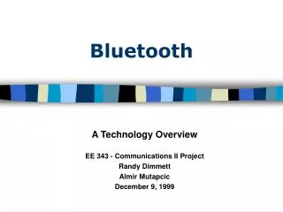
Bluetooth An overview
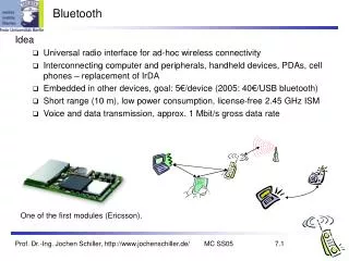
What is Bluetooth Bluetooth is a universal radio interface in the 2.4 GHz frequency band that enables electronic devices to connect and communicate wirelessly via short-range (10-100 m), ad-hoc networks. Key Features : • Peak data rate : 1 Mbps • Low power : peak tx power <= 20 dBm • Low cost : target is $5-10 per piece • Ability to simultaneously handle both voice and data • Line of sight not required
Bluetooth History • Invented in 1994 by L. M. Ericsson, Sweden • Named after Harald Blaatand “Bluetooth”, king of Denmark 940-981 A.D. • Bluetooth SIG founded by Ericsson, IBM, Intel, Nokia and Toshiba in Feb 1998 • More than 1900 members today • Bluetooth version 1.0 and 1.1 have been released
Cordless headset mouse Cell phone Motivation for Bluetooth • Ubiquitous Computing environment of intelligent networked devices • Mobile access to LANs/Internet • Home Networking • Automatic Synchronization of data • Voice applications - hands-free headset Started as a Cable replacement technology
System Challenges • Work across a diverse set of devices with varying computing power and memory • Dynamic environment - the number, location and variety of devices changing - connection establishment, routing and service discovery protocols have to take this into consideration • Unconscious connection establishment • Size of the implementation should be small. The power consumption should not be more than a fraction of the host device .
IP Control Data System Architecture The Radio, Baseband andLink Manager are on firmware. The higher layers could be in soft- ware. The interface is then through the Host Controller (firmware and driver) The HCI interfaces defined for Bluetooth are UART, RS232 and USB. Applications SDP RFCOMM Audio L2CAP Link Manager Baseband RF Bluetooth Protocol Stack
Bluetooth Air Interface Piconet channel definition Physical link definition Packet definition
ISM Band Global Availability License Free 2,400-2,483.5 MHz in Europe and US 2,471-2,497 MHz in Japan Frequency Hopping Interference from baby monitors, garage door openers, cordless phones and microwave ovens. Spread-Spectrum for interference suppression FH supports low power, low cost radio implementations Choices made
Frequency Hopping 1Mhz 79 1 83.5 Mhz • Divide Frequency band into 1 MHz hop channels • Radio hops from one channel to another in a pseudo -random manner as dictated by a hop sequence • The instantaneous (hop) bandwidth remains small • Narrow band interference rejection
m s Piconets, Masters and Slaves • In principle each unit is a peer with the same hardware capabilities • Two or more Bluetooth units that share a channel form a piconet • One of the participating units is becomes the master (by defn the unit that establishes the piconet). • Participants may change roles if a slave unit wants to take over as master • Only one master in a piconet. • Upto 7 slaves
Piconet Channel • The piconet channel is represented by a pseudo-randomhopping sequence (through 79/23 RF frequencies) • The hopping sequence is unique for the piconet and is determined by the device address of the master of the piconet. The phase is determined by the master clock. • Channel is divided into time slots - 625 microsecs each . • Each slot corresponds to a different hop frequency. • Time Division Duplex - master and slave alternately transmit/listen. • Packet start aligned with slot start
Piconet Channel m s1 625 sec f2 f3 f1 f4
Physical Link • Synchronous Connection Oriented (SC0) Link : - symmetric point-to-point link between m and s - reserved 2 consecutive slots at regular intervals - master can support upto 3 simultaneous SCO links - mainly for audio/voice - never retransmitted • Asynchronous Connection-less (ACL) Link : - symmetric/asymmetric - point-to-multipoint between master and all slaves - on a per-slot basis (polling scheme for control) - only one ACL link per piconet - packets retransmitted (ARQ)
Packets • All data on the piconet channel is conveyed in packets • 13 packet types are defined for the Baseband layer - Control packets (ID, NULL, FHS, POLL) - Voice packets (SCO) - Data packets (ACL) • Multi-slot packets (1/3/5) : To support high data rates. Packets always sent on a single-hop carrier – that for the first slot. After multi-slot packet revert to original hop sequence. • Packet format - (68/72 bits) Access Code, (54 bits) Header, (0-2745 bits) Payload.
Packet Format 54 bits 72 bits 0 - 2745 bits Access code Header Payload SCO ACL Voice data header CRC Single-slot packets 64 kbps Unprotected/ 1/3 or 2/3 FEC Never retransmitted Robust CVSD encoding used 1/3/5 slot packets Unprotected/ 2/3 FEC ARQ scheme – retran- smit lost data pkts
Access Code Access code is used for timing synchronization, inquiry and paging. There are 3 types of access codes • Channel Access Code (CAC) : Used to identify a unique piconet. Derived from the device address of the master of the piconet. All “normal” (non inquiry and paging) packets on the piconet will use the CAC. • Device Access Code (DAC) : Used for paging procedure (initial synchronization). Derived from the device address of the slave. • Inquiry Access Code : Used for inquiry procedure (to get device addresses). 2 types : Generic and Device IACs
Header • Addressing (3) : Max 7 slaves per piconet • Packet type (4) : 13 packet types (some unused) • Flow control (1) • 1-bit ARQ (1) : Broadcast packets are not Acked • Sequencing (1) : for filtering retransmitted packets • HEC (8) : Verify Header Integrity Total = 18 bits Encode with 1/3 FEC to get 54 bits
Error Correction/Flow Control • Error Correction - 1/3 FEC - 2/3 FEC - ARQ (Retransmit till Ack is received/ timeout) • Flow Control - FIFO queues at TX and RX - If RX queue is full the flow control bit is set in the header of the next packet sent. - The TX freezes its FIFO queue till the bit is reset.
NETWORKING Connection Establishment Piconet Communication Scatternet Communication
Connection Establishment Two step process : Inquiry – to get device addr Paging – for Synchronization Inquiry : Uses the Inquiry hop sequence and the IAC (DIAC or GIAC) Paging : Uses the Paging hop sequence and the DAC of the device to be paged
Connection Establishment - Inquiry No master and slaves at this point Inquiry pkt Inquiry Scan Inquiry FHS pkt Inquiry Response Device A Device B
Connection Establishment - Paging Master Slave Page pkt Page Page Scan ID pkt Slave Page Response Master Page Response FHS pkt Uses FHS to get CAC and clk info ID pkt Assigns active addr POLL NULL Connected Connected
Connection Establishment times Connected Inquiry Paging Typical 5.12 s 0.64 s Max 15.36 s 7.38 s
Connection Modes • Active Mode : Device actively participates on the piconet channel Power Saving modes • Sniff Mode : Slave device listens to the piconet at a reduced rate . Least power efficient. • Hold Mode : The ACL link to the slave is put on hold. SCO links are still supported. Frees capacity for inquiry, paging, participation in another piconet. • Park Mode : The slave gives up its active member address. But remains synchronized (beacon channel). Listens to broadcasts. Most power efficient.
Intra-piconet communication The master controls all traffic on the piconet SCO link - reservation The master allocates capacity for SCO links by reserving slots in pairs. ACL link – polling scheme The slave transmits in the slave-to-master slot only when it has been addressed by its MAC address in the previous master-to-slave slot. Therefore no collisions.
Device Addressing • Bluetooth Device Address (BD_ADDR) unique 48 bit address • Active Member Address (AM_ADDR) - 3 bit address to identify active slave in a piconet - MAC address of Bluetooth device - all 0 is broadcast address • Parked Member Address (PM_ADDR) - 8 bit parked slave address
Why Scatternets A group of overlapping piconets is called a scatternet • Users in a piconet share a 1 Mbps channel – individual throughput decreases drastically as more units are added • The aggregate and individual throughput of users in a scatternet is much greater than when each user participates on the same piconet • Collisions do occur when 2 piconets use the same 1 MHz hop channel simultaneously. As the number of piconets increases, the performance degrades gracefully
Inter-piconet communication • A unit may particpate in more than one piconet on a TDM basis. • To participate on a piconet it needs the master’s identity and the clock offset. • While leaving the piconet it informs the master • The master can also multiplex as slave on another piconet. But all traffic in its piconet will suspended in its absence.
Architecture Overview Link Manager L2CAP SDP and RFCOMM
IP Control Data System Architecture The Radio, Baseband andLink Manager are on firmware. The higher layers could be in soft- ware. The interface is then through the Host Controller (firmware and driver) The HCI interfaces defined for Bluetooth are UART, RS232 and USB. Applications SDP RFCOMM Audio L2CAP Link Manager Baseband RF Bluetooth Protocol Stack
Link Manager • LMP (Link Manager Protocol) basically consists of a number of PDUs sent in the baseband payload. • LMP packets can be recognised by the L_CH field in the baseband header. • Link Manager handles - Piconet management (attach/detach slaves, master- slave switch) - Link Configuration (low power modes, QoS, packet type selection) - Security
L2CAP Logical link and adaptation protocol • Only ACL links • Concept of L2CAP channels and Channel ids – analogous to sockets in TCP/IP • Functions • Protocol multiplexing • Segmentation and reassembly • QoS specifications • Signalling channel for connection request, config etc
Higher layers SDP Service Discovery Protocol – runs on a client server model. Each device runs only one SDP server and one client may be run for each application. RFCOMM Transport protocol providing serial data transfer
References • Jaap Haarsten, Bluetooth – The universal radio interface for ad-hoc wireless connectivity, Ericsson Review, no. 3, 1998. www.ericsson.se/review • Palowireless www.palowireless.com/infotooth/tutorial • Aman Kansal, Connection Establishment in Bluetooth • The official bluetooth site - www.bluetooth.com • http://opensource.nus.edu.sg/projects/bluetooth/