Download
1 / 31
980 likes | 2.72k Views
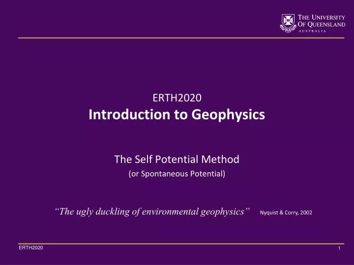
ERTH2020 Introduction to Geophysics. “The ugly duckling of environmental geophysics”. Nyquist & Corry, 2002. The Self Potential Method (or Spontaneous Potential). Self Potential Method. Passive geophysical method (like gravity/magnetics). One of the oldest geophysical methods.

E N D
ERTH2020Introduction to Geophysics “The ugly duckling of environmental geophysics” Nyquist & Corry, 2002 The Self Potential Method (or Spontaneous Potential)
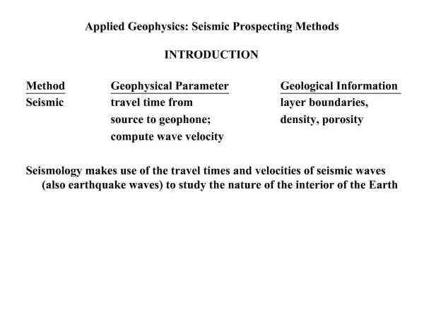
Self Potential Method • Passive geophysical method (like gravity/magnetics) • One of the oldest geophysical methods. • First measurement by Fox (1830) in Cornwell, UK, over sulphide vein mineralisation. • Frequently used since the 1920s as a (secondary) tool for base-metal exploration and also for detecting subsurface fluid-flow. • Involves measurement of electric potentials (voltages) at specific points on the surface or downhole (self-potential stations). • Required: volt-meter, non-polarising electrodes. • Natural potential differences generally exist between any two points on the ground (associated with electrical currents in the subsurface). • Mostly used qualitatively due to lack of quantitative models but this is changing rapidly (complex causative sources of self-potential signal). c.f. Revil & Jardani, 2013, pp. 14
Self Potential Method • Applications: • for mineral exploration • geothermal applications • groundwater investigation • formation evaluation in the oil and gas industry • to detect fluid flow in fractured rocks and gas reservoirs • engineering applications to detect dam fractures and seepage • and others … Revil & Jardani, 2013
Self Potential Method Revil & Jardani, 2013, p. 2
Self Potential Method • Development of non-polarising electrodes (porous-pot) in 1865 by M.C. Matteucci, Greenwich Observatory. • Measurements in mV (streaming potential) to several V (mineralisation potential). Revil & Jardani, 2013, p. 2
Self Potential Method • High Impedance Potentiometer (Voltmeter). • Impedance (Resistance) has to be at least 10x higher than the ground between the electrodes to avoid current leakage in the voltmeter. • Impedance range from 105Ohm.m to 1012 Ohm.m for very resistive ground (ice, permafrost, crystalline rock) Revil & Jardani, 2013, p. 2
Self Potential Method • SP-Response associated with an aquifer test. • Water was pumped from one well and injected into another. • Time variation of measured SP data due to ground water flow associated with pumping and injection tests (at one SP station). The SP response is sensitive to ground water flow triggered through the pumping test Data obtained prior to pumping. Transient phase during pumping Steady-state phase Recovery phase Steady state phase thermal drift Jardani, A. et al., 2008; c.f. http://en.wikipedia.org/wiki/Aquifer_test
Self Potential Method • Data acquisition. • Also used is the “star-approach” where first the potential differences between a set of base stations is determined. • Subsequently, each base is used as the local reference of profiles which are radially distributed about this station. Revil & Jardani, 2013, p. 4
Self Potential Method • Data acquisition. • Large-scale mapping frequently uses a loop network approach • One base station is chosen as the reference and measurements are taken with scanning electrodes at SP stations. Revil & Jardani, 2013, p. 4
Self Potential Method Data processing. Revil & Jardani, 2013, p. 6
Self Potential Method Mechanismsgoverning the occurrence of SP signals can be classified as follows: • Diffusion potentials (liquid-junction potential) • ShalePotentials(Nernst potential) • Bioelectric potentials • Mineral potentials • Streaming potentials (zeta potential) Background/Noise Geophysical Exploration All mechanisms are fundamentally electrochemicalin nature Telford et al, 1991, pp. 283
Self Potential Method • Diffusion potentials (liquid-junction potential) • associated with gradients in concentrations of ionic species in the ground that set up diffusion potentials. • Shale Potential(Nernst potential) • (special case of diffusion potential) electrodes are immersed in a homogeneous solution but with different concentrations at the electrodes. • Bioelectric potentials • ion selectivity and water pumping action of plant roots can create SP anomalies. • Mineral potentials • (apparently) arise from geochemical oxidation-reduction (redox) reactions, equivalent to the galvanic cell defined in electrochemistry. • Streaming potentials (zeta potential) • arise when water or other fluids flow through sand, porous rock, moraines, basalts, etc. Nyquist and Corry, 2002; Telford et al, 1991, pp. 283
Self Potential Method • Diffusion potentials • associated with gradients in concentrations of ionic species in the ground that set up diffusion potentials. • Anions & Cations with different mobilities result in different diffusion rates electric potential (faster moving ions of one charge will begin to outpace the ions of the opposite charge. The resultant electric field is just what is required to speed up the slower moving ions and maintain electro-neutrality). • In equilibrium, the diffusion potential, , is given by: viaNernst-Planck equation flux density, : diffusion coefficient,ionic species and electric field . anion/cation mobilities; electric charge/ion, universal gas constant; is the temperature; is the Faraday constant; , solution concentrations Nyquist and Corry, 2002; Telford et al, 1991, pp. 283
Self Potential Method Sandstone and Shale, marlimillerphoto.com • Shale Potential(Nernst potential) • when two identical electrodes are immersed in a homogeneous solution but with different concentrations at the electrodes. • Shale potential develops at the boundary between shale and sandstone because shale is more permeable to Na+ ions than Cl- ions. • The net effect is that voltages recorded adjacent to shale are higher than voltages recorded adjacent to sandstone. (Nernst potential) In general, Diffusion/Nernst potentials can create anomalies in the tens of millivolts, and is just a source of noise in most SP surveys. Nyquist and Corry, 2002; Telford et al, 1991, pp. 283
Self Potential Method • Bioelectric potentials • ion selectivity and water pumping action of plant roots can create SP anomalies. • Bioelectric anomalies can reach hundreds of millivolts. • Abrupt changes in SP have been noted in the field when the vegetation changes (commonly associated with changes in soil composition). • Background/Noise in conventional geophysics, but useful to map electrical potential gradients which governs water and nutrients uptake by plants. landviser.net landviser.net Nyquist and Corry, 2002
Self Potential Method • Mineral potentials • arise from geochemical oxidation-reduction (redox) reactions, equivalent to a ‘battery’. Lowrie, 1997, p. 209
Self Potential Method • Mineral potentials • arise from geochemical oxidation-reduction (redox) reactions, equivalent to a ‘battery’. • After Sato & Mooney (1960): • Cathodic reaction above the water table • Chemical reduction electron gain • Anodic reaction at depth below water table • Chemical oxidation electron loss • The ore body itself functions only to transport electrons from anode to cathode • SP anomaly associated with ore bodies can be in the order of a few hundreds of millivolts to over 1 V Nyquist and Corry, 2002; Revil & Jardani, 2013, p.72
Self Potential Method • Mineral potentials () • arise from geochemical oxidation-reduction (redox) reactions, equivalent to a ‘battery’. Calculated via the NernstPotential Used very successfully in base metal exploration. Note: the Sato & Mooney (SM) “battery” model cannot fully explain all observed phenomena: • Large amplitudes > 800 mV • (Max SM model ~ 800 mV) • Large measured voltage gradients • (SM model predicts smooth gradients) • Anomalies of ore bodies completely below the water table • Lack of positive pole • Measured data always negative for completely drilled body Nyquist and Corry, 2002;
Self Potential Method • Mineral potentials () • Typical contour map and profile over an ore body producing a large SP anomaly • The negative maximum lies directly over the sulphide mass • Over steep topography, the centre will usually be displaced Telford et al, 1991, pp. 298
Self Potential Method • Mineral potentials () • SP anomaly across a sulfide ore-body at Sariyer, Turkey. • Pyrite & chalcopyrite occur in varying concentrations within a massive deposit, hosted in Andesite and below Devonian schist. • The area shows steep topography, shifting the SP anomaly downhill Reynolds, 2011, pp. 363
Self Potential Method • Mineral potentials () Each of the various mineralisation zones may be represented by a sphere whose SP anomaly contributes to the total anomaly observed Reynolds, 2011, pp. 363
Self Potential Method • Streaming potentials (electrokinetic or zeta potential) • arise when water or other fluids flow through sand, porous rock, moraines, basalts, etc. • This is observed when a solution of electrical resistivity and viscosity is forced through a capillary or porous medium. • The resultant potential difference between the ends of the passage is adsorption (zeta) potential pressure difference : solution dielectric constant • In areas of high rainfall, steep topography and porous rock, streaming potentials can be of large amplitude. • E.g. A 2693-mV SP anomaly on Agadak Volcano (Adak Island, Alaska) is attributed to streaming potentials Telford et al, 1991, pp. 283
Self Potential Method • Streaming potentials. A vertical boundary with upwelling from the right Pumping from a well. Horizontal boundary flow along different interfaces . Reynolds, pp. 351
Self Potential Method Thermal gradient and SP profiles over the Dome Fault Zone, Roosevelt Hot Springs (Utah) associated with Mineral, Streaming and Diffusion Potentials. • Streaming potentials. Correspondence of broad SP anomaly and thermal gradient profile suggest a thermal origin for the SP anomaly. Pos. anomaly (geothermal activity) The geothermal SP anomaly results from Streaming Potentials driven by convection cells, but also due to Diffusion Potentials due to temperature gradient. Neg. anomaly (Alunite & Pyrite) Arrows denote points at which faults cross the SP survey line. Reynolds, 2011, pp. 359
The Electric Double layer • The Zeta potential is the potential drop across the mobile part of the double layer: • i.e. it is the electric potential in the interfacial double layer (DL) at the location of the slipping plane versus a point in the bulk fluid away from the interface. ζ is positive if the potential increases from the bulk of the liquid phase towards the interface. http://en.wikipedia.org/wiki/Zeta_potential
The Electric Double layer Electric double-layer The -potential develops across boundaries between a fluid electrolyte and mineral grains in fractured rock and porous media. The more negative the -potential the more positive ions are transported with the flow and thus the greater the net transport of negative charge ions. • Aggregation of excess charge on each side of the interface electrical double layer. • The mobile part of the electrical double layer is dragged along with the fluid-flow transport of electric charge with the flow. • The amount of charge transported is directly related to the -Potential. Costar et al., 2008, pp. 15
Application: Sinkhole Detection Picture of Sinkhole A1, which has a diameter of 10 meters. The depth of the depression is about 2 m Revil & Jardani, 2013, p.161
Application: Sinkhole Detection Revil & Jardani, 2013, p.162
Application: Sinkhole Detection SP Stations (+) DC Resistivity Survey Visible Sinkholes (Interpreted) “Crypto “Sinkholes Revil & Jardani, 2013, p.164
Application: Sinkhole Detection SP Contour Map & DC Resistivity Section Revil & Jardani, 2013, p.165
References • Revil, A., Jardani, A.: “The Self-Potential Method", 2013, Cambridge. • Nyquist, J. E., Corry, E. C., “Self-potential: The ugly duckling of environmental geophysics”, 2002, The Leading Edge, pp. 446. • Jardani, A. et al., “Reconstruction of the Water Table from Self-Potential Data: A Bayesian Approach”, 2008, Ground Water, pp. 213 • Telford, W.M, Geldart, L.P., Sheriff, R.E.: “Applied Geophysics”, 1991, Cambridge University Press • Lowrie, W. “Fundamentals of Geophysics”, 1997, Cambridge University Press • Reynolds, J.M., "An Introduction to Applied and Environmental Geophysics", 2011, John Wiley & Sons • Costar A., Heinson G., Wilson T., Smit, Z.,:“Hydrogeophysical mapping of fracture orientation and groundwater flow in the Eastern Mount Lofty Ranges, South Australia”, 2009, DWLBC Report, Gov. South Australia • Fagerlund F., Heinson G., “Detecting subsurface groundwater flow in fractured rock using self-potential (SP) methods”, 2003, Environmental Geology, 43, pp. 782