Download
1 / 19
200 likes | 272 Views
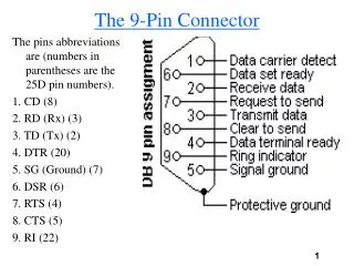
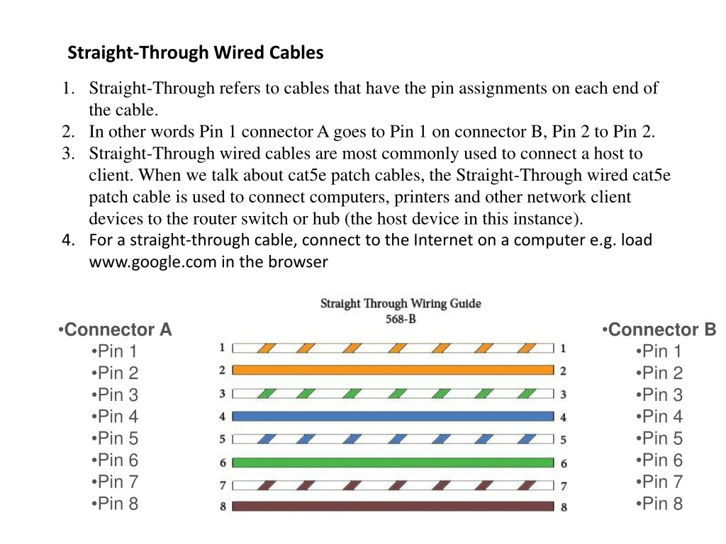
Straight-Through Wired Cables. Straight-Through refers to cables that have the pin assignments on each end of the cable. In other words Pin 1 connector A goes to Pin 1 on connector B, Pin 2 to Pin 2.

E N D
Straight-Through Wired Cables Straight-Through refers to cables that have the pin assignments on each end of the cable. In other words Pin 1 connector A goes to Pin 1 on connector B, Pin 2 to Pin 2. Straight-Through wired cables are most commonly used to connect a host to client. When we talk about cat5e patch cables, the Straight-Through wired cat5e patch cable is used to connect computers, printers and other network client devices to the router switch or hub (the host device in this instance). For a straight-through cable, connect to the Internet on a computer e.g. load www.google.com in the browser • Connector A • Pin 1 • Pin 2 • Pin 3 • Pin 4 • Pin 5 • Pin 6 • Pin 7 • Pin 8 • Connector B • Pin 1 • Pin 2 • Pin 3 • Pin 4 • Pin 5 • Pin 6 • Pin 7 • Pin 8
Crossover Wired Cables Crossover cables are most commonly used to connect two hosts directly. Examples would be connecting a computer directly to another computer, connecting a switch directly to another switch, or connecting a router to a router. For a crossover cable, connect 2 computers. From one computer, issue a ping request to the other. While in the past when connecting two host devices directly a crossover cable was required. Now days most devices have auto sensing technology that detects the cable and device and crosses pairs when needed. • Connector A • Pin 1 • Pin 2 • Pin 3 • Pin 4 • Pin 5 • Pin 6 • Pin 7 • Pin 8 • Connector B • Pin 1 • Pin 2 • Pin 3 • Pin 4 • Pin 5 • Pin 6 • Pin 7 • Pin 8
Rollover Wired Cables Rollover wired cables most commonly called rollover cables, have opposite Pin assignments on each end of the cable or in other words it is "rolled over". Pin 1 of connector A would be connected to Pin 8 of connector B. Pin 2 of connector A would be connected to Pin 7 of connector B and so on. Rollover cables, sometimes referred to as Yost cables are most commonly used to connect to a devices console port to make programming changes to the device. Unlike crossover and straight-wired cables, rollover cables are not intended to carry data but instead create an interface with the device. • Connector A • Pin 1 • Pin 2 • Pin 3 • Pin 4 • Pin 5 • Pin 6 • Pin 7 • Pin 8 • Connector B • Pin 1 • Pin 2 • Pin 3 • Pin 4 • Pin 5 • Pin 6 • Pin 7 • Pin 8
Node: A network is a collection of computers or other devices, commonly called nodes, that are able to communicate with each other. Hub: The most common type of network (especially in the home) is the Ethernet network, where all nodes are connected to a central device. In its simplest form this central node is called a hub. Basically, a hub is a box with lots of connections (sockets) for Ethernet cables. The hub repeats all messages it receives to all connected nodes, and these nodes filter out only the messages that are intended for them. This filtering takes place at the Ethernet level: incoming messages carry the Ethernet network address of the intended recipient. A problem with this approach is that hubs generate a lot of traffic, especially on larger networks. Most of this traffic is wasted, since it is intended for only one node but it is sent to all nodes on the network. Switch: A switch still connects all nodes to each other, like a hub, but is more intelligent in which messages are passed on to which node. A switch examines incoming Ethernet messages to see which node is the intended recipient, and then directly (and only) passes the messages to that node. This way other nodes do not unnecessarily receive all traffic. Since switches are more expensive than hubs, a low-traffic part of the network could be set up using a hub, with the more high-traffic nodes being interconnected to the switch.
Segment: A large network can be divided into multiple parts which are called segments. Each segment can use its own network protocol, security rules, firewalls and so on. Nodes on different segments cannot directly communicate with each other. To make this possible, a bridge is added between the segments. Bridge: The bridge lets packet pass that are destined for a host on the other side. This seems to turn the two segments into one big network again, but there is an important difference. Data packets generated on one segment and intended for that same segment are not passed to the other segment. This saves on data transmission on the network as a whole.
Routers and routing Routers and gateways A router is connected to two different networks and passes packets between them, as shown in figure 4 to the right. In a typical home network, the router provides the connection between the network and the Internet. A gateway is the same as a router, except in that it also translates between one network system or protocol and another. The NAT protocol for example uses a NAT gateway to connect a private network to the Internet. Routing messages between networks When a node on one network needs to send a message to a node on another network, this packet will be picked up by the router and passed on to the other network. Many nodes are programmed with a so-called 'default gateway', which is the address of the router that is to take care of all packets not for other nodes on the same network.
IPv4 supports three different types of addressing modes.: • Unicast Addressing Mode: • In this mode, data is sent only to one destined host. The Destination Address field contains 32- bit IP address of the destination host. Here the client sends data to the targeted server:
ers: Broadcast Addressing Mode: In this mode, the packet is addressed to all the hosts in a network segment. The Destination Address field contains a special broadcast address, i.e. 255.255.255.255. When a host sees this packet on the network, it is bound to process it. Here the client sends a packet, which is entertained by all the Servers:
Multicast Addressing Mode: This mode is a mix of the previous two modes, i.e. the packet sent is neither destined to a single host nor all the hosts on the segment. In this packet, the Destination Address contains a special address which starts with 224.x.x.x and can be entertained by more than one host. Here a server sends packets which are entertained by more than one servers. Every network has one IP address reserved for the Network Number which represents the network and one IP address reserved for the Broadcast Address, which represents all the hosts in that network.
Hierarchical Addressing Scheme IPv4 uses hierarchical addressing scheme. An IP address, which is 32-bits in length, is divided into two or three parts as depicted: A single IP address can contain information about the network and its sub-network and ultimately the host. This scheme enables the IP Address to be hierarchical where a network can have many sub-networks which in turn can have many hosts.
Subnet Mask The 32-bit IP address contains information about the host and its network. It is very necessary to distinguish both. For this, routers use Subnet Mask, which is as long as the size of the network address in the IP address. Subnet Mask is also 32 bits long. If the IP address in binary is ANDed with its Subnet Mask, the result yields the Network address. For example, say the IP Address is 192.168.1.152 and the Subnet Mask is 255.255.255.0 then: This way the Subnet Mask helps extract the Network ID and the Host from an IP Address. It can be identified now that 192.168.1.0 is the Network number and 192.168.1.152 is the host on that network.
Pv4 Addressing system is divided into five classes of IP Addresses. Class A Address The first bit of the first octet is always set to 0 (zero). Thus the first octet ranges from 1 – 127, i.e. Class A addresses only include IP starting from 1.x.x.x to 126.x.x.x only. The IP range 127.x.x.x is reserved for loopback IP addresses. The default subnet mask for Class A IP address is
Class B Address An IP address which belongs to class B has the first two bits in the first octet set to 10, i.e. Class B IP Addresses range from 128.0.x.x to 191.255.x.x. The default subnet mask for Class B is 255.255.x.x.
Class C Address The first octet of Class C IP address has its first 3 bits set to 110, that is: Class C IP addresses range from 192.0.0.x to 223.255.255.x. The default subnet mask for Class C is 255.255.255.x.
Class D Address Very first four bits of the first octet in Class D IP addresses are set to 1110, giving a range of: Class D has IP address range from 224.0.0.0 to 239.255.255.255. Class D is reserved for Multicasting. In multicasting data is not destined for a particular host, that is why there is no need to extract host address from the IP address, and Class D does not have any subnet mask.
Class E Address This IP Class is reserved for experimental purposes only for R&D or Study. IP addresses in this class ranges from 240.0.0.0 to 255.255.255.254. Like Class D, this class too is not equipped with any subnet mask.