Download
1 / 35
350 likes | 537 Views
CCLRC Adams Institute Cockcroft Institute High Power RF Faraday Partnership Imperial College London Brunel University University of Durham University of Glasgow University of Lancaster University of Liverpool University of Oxford University of Sheffield University of Southampton

E N D
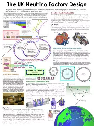
CCLRC Adams Institute Cockcroft Institute High Power RF Faraday Partnership Imperial College London Brunel University University of Durham University of Glasgow University of Lancaster University of Liverpool University of Oxford University of Sheffield University of Southampton University of Warwick UK Neutrino Factory C.R. Prior CCLRC-ASTeC and Trinity College Oxford On behalf of the UK Neutrino Factory Collaboration
Neutrino Factory • NF covers every aspect of advanced accelerator study • Aim is 1021 neutrinos per year • Intense proton beams with very short bunch length (~1ns) • Secondary pion beam • Low production rate • Targets capable of handling multi-MW of beam power • Tertiary muon beams (lifetime 2.2μs at rest) • Fast acceleration • Decay rings handling large muon beam power • Neutrinos are a quarternary beam • New concepts • Ionization cooling • FFAG accelerators (large acceptance, rapid acceleration) n n n n
Time Line • 1999 Inauguration of series of annual Neutrino Factory Workshops. • Basic parameters set • RAL collaboration with CERN • UK design of synchrotron proton drivers • PPARC funded UKNF study 2003-2006 • International Scoping Study (ISS) 2005-2006 • UK scientists playing a major role • Identification of a self-consistent NF scenario • Baseline design established • The future • Further UKNF study 2007-2010 • International Design Study, probably UK led.
UKNF 2003-2006 • WP1 Conceptual Design Study • Designs for whole accelerating structure identified • WP2 Proton Driver Front End Test Stand • Fundamental proton driver R&D • WP3 Target R&D • WP4 Preparation for International Design Study • Several new young enthusiastic recruits to Accelerator Physics. • Much progress has been made in all areas. • The UK is at the forefront of NF studies and in a position to lead and direct NF research.
UKNF 2007-2010 • WP1 Conceptual Design Study • Detailed analysis of integrated accelerator facility in accordance with ISS recommendations • WP2 Proton Driver Front End Test Stand • Through to completion • WP3 Target R&D • Establish viability of a solid target solution • WP4 Development of High Gradient RF Cavities • WP5 Survey and Geological Investigation • Explore feasibility of RAL as a site for a Neutrino Factory • WP6 International Design Study • IDR 2010, CDR 2012
WP1 Conceptual Design Study • Proton driver • UK designs at 5GeV, 8GeV, 10Gev, 15GeV, 30GeV • Pion decay/muon capture • Optimised solenoid scheme • Recent new ideas for phase rotation to capture both µ+ and µ- • Cooling • Cooling ring designed • New modelling code under development • Novel cooling schemes under investigation • Muon Acceleration • New codes developed • Investigation of J-PARC scheme (in collaboration) • UK lattices for first-ever isochronous FFAGs • Muon storage and neutrino production • UK designs for triangular and bow-tie rings • Suitable detector sites identified for a facility based at RAL
Proton Drivers • ISS baseline: • 4MW beam power • 50 Hz repetition rate • Energy 5-15GeV • 1-5 bunches per pulse, each compressed to 1-2ns rms • 20μs delay between output of bunches to target • UKNF 10GeV design meets all requirements 10 GeV FFAG Radius=127.6m 180 MeV H- linac 218m 3 GeV RCS Booster Radius=63.788m 3 or 5 proton bunches 221m
Proton Drivers • In-depth analysis required • Potential difficulties • Beam chopping • Beam injection into booster synchrotron • Bunch compression to ~1ns rms • FFAG itself • Develop 3D modelling codes (including space charge) for synchrotrons and for FFAGs • R&D: design and build an electron model of a non-scaling proton FFAG • Funding being sought elsewhere 10 GeV FFAG 180 MeV H- linac 218m 3 GeV RCS Booster 3 or 5 proton bunches 221m
Pion Decay/Muon Capture Distributed code for optimisation of solenoid capture channel Optimise for 0.2 muons/proton through capture channel. Phase rotation and bunching systems prior to cooling. Choice of Proton Driver Energy New scheme to capture equal quantities of both sign muons
Muon Acceleration • Initial stages of muon acceleration in linac and RLA (dogbone) • One or more FFAGs to reach final energy (20-40GeV) • Both μ– and μ+ accelerated • Muon beam has very large emittance (~30,000 π mm.mrad) Schematic of ISS baseline for muon acceleration. Other layouts are under consideration. Beam trajectories in triplet FFAG
Transverse emittance = 1 π mm.mrad 3 12 22 Kinetic energy [GeV] 10 2 0 New Modelling Code: end-end simulation FFAG RLA Linac RF phase/2π • Transverse emittance = 30,000 π mm.mrad 3 12 22 Kinetic energy [GeV] FFAG Linac RLA 0 2 10
Electron FFAG test model Essential R&D of a non-scaling FFAG 10-20 MeV electron model to test theory and demonstrate beam transport Beam dynamics and simulation carried out under UKNF WP1 Bid for money for construction submitted to Basic Technology Fund. EMMA EMMA fed by ERLP injector at Daresbury Laboratory
Triangular design Bow-tie design ν Injection ν ν ν Muon Decay Rings 53° Circumference for both rings = 1608m 425m production straights • Advantages of Bow-tie design • smaller depth (300 m compared with 435 m). • higher efficiency (52.6 % compared with 49.6%). • greater choice of the opening angle around 50°. • But needs a scheme to remove the beam polarization. Two parallel rings, one for each muon sign, in each tunnel, with μ±bunches interleaved in time.
Detector Sites for NF at RAL New Work Package WP5 to explore geology and sites for decay rings
Ion source 70 mA, 2 ms, 10 % dc 3 Solenoid LEBT RFQ, 324 MHz, 3 MeV MEBT, chopper WP2 Proton Driver R&D: The Front End Test Stand Creating gaps in H- micro-pulse train (chopping) is essential for low-loss, high intensity, beam accumulation
Front-end Test Stand • ASTeC and EU FP6/HIPPI funded • H- ion source: development goals: • Double output current 35mA →70mA • Increase pulse length 200µs → 2ms • Improve emittance • Maximise lifetime • Design of Solenoid-based LEBT completed • Production of 324MHz RFQ • Cold model almost finished • Preparing a computer controlled bead pull system for field measurement • Fast beam chopper • Electronics ready • Alternative beamline optics under study • Diagnostics • Laser-wire system for profile measurement from different angles ISIS ion source at RAL 2 copper “quadrants” of the RFQ cold model waiting for brazing A generic project – could be used for any proton driver
Radio Frequency Quadrupole Linac • A 324MHz klystron has been ordered from Toshiba for delivery towards the end of 2006. • A cold model RFQ is under construction. 0.5m long, it models all significant features of the full 4m design Aluminium machining model Design of the 4 vane RFQ cold model
Fast and slowchopper modules Chopper 1 (fast transition) Chopper 2 / Beam dump(slower transition) BEAM FETS Fast Beam Chopper A novel tandem chopper technique has been developed at RAL to overcome the conflicting requirements of fast rise time (< 2ns) and long flat-top (up to 100 s). • A ‘fast’ chopper, with short rise time but limited flat-top, removes 2-3 microbunches. • In the gap created, a ‘slow’ chopper is switched on, with longer rise time and flat-top, able to remove a succession of micropulses (typically ~100). • The gap in the bunch train is needed for low-loss injection and extraction in the accumulator rings.
WP3 Target Studies • Potential Neutrino Factory show-stopper • Target station small nuclear power station, need to be in secure nuclear site • Radiation safety very important • Target feasibility not yet demonstrated • UKNF focus on solid targets • Radiation safety “easier” + more World experience exists • Issues: • Shock – simulations suggest could break target in 1 pulse • Temperature rise – would melt target in < 50 pulses • Radiation damage – could break target in many pulses Shock Studies • UKNF has developed world-leading expertise • A shock test facility has been built without a 4MW proton driver! • A much better understanding of shock has been acquired UK solid target work is based on a moving target – each “rod” is exposed to the proton beam only once every 3 sec
50kV, 8kA pulsed p/s for ISIS kicker magnets Pulse: rise time ~100ns, 800ns flat top Tested 0.5mm Ta & W wires W after testing at 5MW. Breaks caused by removal, not testing Ta at 2000K
Some Results of 0.5 mm diameter wires Equivalent Target “Equivalent Target”: This shows the equivalent beam power (MW) and target radius (cm) in a real target for the same stress in the test wire. Assumes a parabolic beam distribution and 4 micro-pulses per macro-pulse, spaced at 30 s.
Target Studies: simulation Code LSDyna • Benchmarked against existing beam data • Used to: • understand shock • relate wires to NF targets • study shock reduction • determine size of effects • study failure mechanisms Codes MARS and GEANT4 • Used to: • predict energy deposition in target • study radiation damage • monitor pion production (cf HARP data) Comparison with tests at ISOLDE
Target Plans 2007-2010 • Results for shock and radiation damage in W look very promising –contrary to widely held belief. • Continue shock measurements and supporting simulations • find limits ■ show reproducibility ■ test different solids • test expected shock dependence ■ temperature dependence • Strengthen case for solid targets –also important for other projects • Engineer realistic mechanism for changing target at 50Hz • including building a model • Study the effect of the 20T capture solenoid field • Engineer a target station around the target: • simulations required of activation, heating, etc • incorporate a beam dump • Considerable expertise with W being developed by ISIS • Maintain ability to contribute to liquid target work (MERIT) • Main deliverable:realistic and defendable solid target solution for a Neutrino Factory
WP4 High Gradient RF Cavities • Experimental and theoretical studies • Achievable accelerating gradient under a few Tesla magnetic fields • Ascertain what can be manufactured with repeatable specifications • Investigate surface factors that limit accelerating gradient • Electro-polishing • Chemical mechanical polishing • Abrasive flow machining • Fabrication: • Examine surface topology and chemical composition • Evaluate effects of fabrication on these properties • High power testing • Collaboration with overseas laboratories (FNAL, LBNL, J-Lab) and industry (Shakespeare Engineering, North Eastern Metal Spinners, e2v, High Power RF Faraday Partnership)
Load RF Power Two couplers Ceramic RF window Water cooling line RF coupler conditioning at SNS in ORNL Cavity Fabrication Process Cavity body
Summary • Aim to complete conceptual NF design in framework of ISS recommendations and in collaboration with IDS, working towards the full (international) conceptual design report in 2012. • Complete proton driver front-end test stand and demonstrate fast, clean, beam chopping. Important for many applications besides NF. • Further studies of solid targets to find a feasible solution for NF. Again, other applications. • Develop techniques for production of reliable high-gradient RF cavities. Generic. • Undertake geological study of suitable site for a Neutrino Factory. • Play a leading role in the International Design Study.
Organisation and summary • Management of UKNF programme • Summary of request
Project management: Conceptual designC. Prior Front-end test standA. Letchford Target studiesR. Edgecock KL UKNF Steering Group High-gradient cavitydevelopmentR. Seviour Site survey &geological studiesM. Warner MICE-UK InternationalDesign StudyR. Edgecock
WP1: NF Conceptual design • Principal deliverable: • Interim design report (IDR) • In context of the International Design Study (IDS) • Resources for the UK contributions to the IDS • Underpins: • UK leadership position • Eventual development of bid to host or to make substantial contributions
WP2: Proton driver f/e test stand • Principal deliverable: • Front-end test stand: • LEBT, RFQ, Chopper, and diagnostics • High-quality chopped beams critical for development of high-power proton driver for the Neutrino Factory • Complementarity: • EU FP6 HIPPI • Future high-power proton facilities (e.g. ISIS upgrade, ESS, …)
WP3: Target studies • Principal deliverable • Conceptual design for NF target station for inclusion in IDR • High-power target key engineering challenge • Require to: • Complete solid-target material studies; • Develop engineering concept of target station
WP4:Development of high-gradient cavities • Principal deliverable: • Robust, reproducible manufacturing process • Completion of IDR requires specification of accelerating gradients in acceleration systems: • Challenge: high-gradient in magnetic field • Requirement: to build many cavities to spec. • To define manufacturing process require: • To understand of effect steps in manufacture have on achievable gradient • To devise cost optimised manufacturing process
WP5: Site survey and geological studies • Site survey: • Essential pre-requisite to preparation of bid to host • Geological studies: • Performance optimum for given cost requires understanding cost of reducing matter density uncertainty
WP6: International Design Study • UK demonstrated international leadership by initiating the ISS • Essential to maintain and enhance this position by • Resources required to: • Allow UK personnel to play key leadership roles in the negotiations leading to the formation of the International Design Study collaboration • Allow UK personnel to play leading roles in the preparation of a successful bid to EU Framework Programme 7
Summary • Resources will allow UKNF to: • Deliver IDR for the Neutrino Factory by 2010 • As a leading member of the IDS collaboration • As a step on the way to producing the NF CDR by 2012 • Carry out a targeted programme of hardware R&D that will: • Establish UK competence in key systems and technologies • Engage appropriately with industry to ensure cost models for CDR are accurate