Download
1 / 1
10 likes | 106 Views
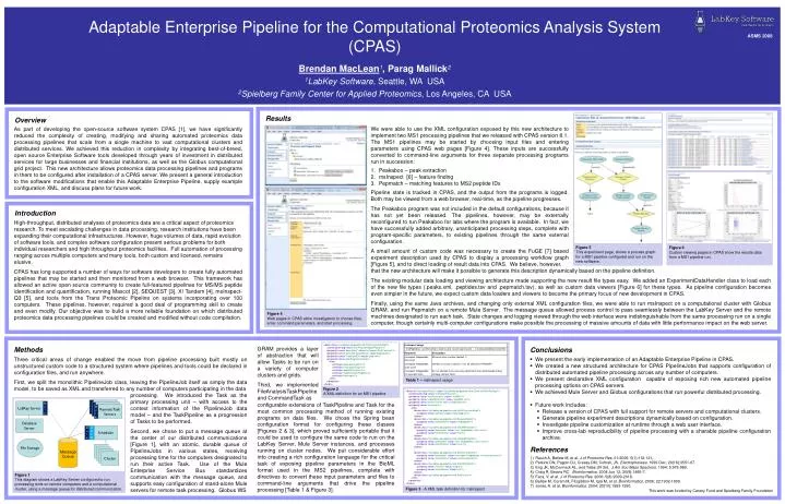
Adaptable Enterprise Pipeline for the Computational Proteomics Analysis System (CPAS) Brendan MacLean 1 , Parag Mallick 2 1 LabKey Software , Seattle, WA USA 2 Spielberg Family Center for Applied Proteomics , Los Angeles, CA USA. ASMS 2008. Mule. GRAM. Scheduler. Cluster. Overview.

E N D
Adaptable Enterprise Pipeline for the Computational Proteomics Analysis System (CPAS) Brendan MacLean1, Parag Mallick2 1LabKey Software, Seattle, WA USA 2Spielberg Family Center for Applied Proteomics, Los Angeles, CA USA ASMS 2008 Mule GRAM Scheduler Cluster Overview Results We were able to use the XML configuration exposed by this new architecture to implement two MS1 processing pipelines that we released with CPAS version 8.1. The MS1 pipelines may be started by choosing input files and entering parameters using CPAS web pages [Figure 4]. These inputs are successfully converted to command-line arguments for three separate processing programs run in succession: Peakaboo – peak extraction msInspect [6] – feature finding Pepmatch – matching features to MS2 peptide IDs Pipeline state is tracked in CPAS, and the output from the programs is logged. Both may be viewed from a web browser, real-time, as the pipeline progresses. The Peakaboo program was not included in the default configurations, because it has not yet been released. The pipelines, however, may be externally reconfigured to run Peakaboo for labs where the program is available. In fact, we have successfully added arbitrary, unanticipated processing steps, complete with program-specific parameters, to existing pipelines through the same external configuration. A small amount of custom code was necessary to create the FuGE [7] based experiment description used by CPAS to display a processing workflow graph [Figure 5], and to direct loading of result data into CPAS. We believe, however, As part of developing the open-source software system CPAS [1], we have significantly reduced the complexity of creating, modifying and sharing automated proteomics data processing pipelines that scale from a single machine to vast computational clusters and distributed services. We achieved this reduction in complexity by integrating best-of-breed, open source Enterprise Software tools developed through years of investment in distributed services for large businesses and financial institutions, as well as the Globus computational grid project. This new architecture allows proteomics data processing pipelines and programs in them to be configured after installation of a CPAS server. We present a general introduction to the software modifications that enable this Adaptable Enterprise Pipeline, supply example configuration XML, and discuss plans for future work. Introduction High-throughput, distributed analyses of proteomics data are a critical aspect of proteomics research. To meet escalating challenges in data processing, research institutions have been expanding their computational infrastructures. However, huge volumes of data, rapid evolution of software tools, and complex software configuration present serious problems for both individual researchers and high throughput proteomics facilities. Full automation of processing ranging across multiple computers and many tools, both custom and licensed, remains elusive. CPAS has long supported a number of ways for software developers to create fully automated pipelines that may be started and then monitored from a web browser. This framework has allowed an active open source community to create full-featured pipelines for MS/MS peptide identification and quantification, running Mascot [2], SEQUEST [3], X! Tandem [4], msInspect-Q3 [5], and tools from the Trans Proteomic Pipeline on systems incorporating over 100 computers. These pipelines, however, required a good deal of programming skill to create and even modify. Our objective was to build a more reliable foundation on which distributed proteomics data processing pipelines could be created and modified without code compilation. Figure 5 This experiment page, shows a process graph for a MS1 pipeline configured and run on the new software. Figure 6 Custom viewing pages in CPAS show the results data from a MS1 pipeline run. that the new architecture will make it possible to generate this description dynamically based on the pipeline definition. The existing modular data loading and viewing architecture made supporting the new result file types easy. We added an ExperimentDataHandler class to load each of the new file types (.peaks.xml, .peptides.tsv and .pepmatch.tsv), as well as custom data viewers [Figure 6] for these types. As pipeline configuration becomes even simpler in the future, we expect custom data loaders and viewers to become the primary focus of new development in CPAS. Finally, using the same Java archives, and changing only external XML configuration files, we were able to run msInspect on a computational cluster with Globus GRAM, and run Pepmatch on a remote Mule Server. The message queue allowed process control to pass seamlessly between the LabKey Server and the remote machines designated to run each task. State changes and logging viewed through the web interface were indistinguishable from the same processing run on a single computer, though certainly multi-computer configurations make possible the processing of massive amounts of data with little performance impact on the web server. Figure 4 Web pages in CPAS allow investigators to choose files, enter command parameters, and start processing. <beanclass="org.labkey.api.pipeline.file.FileAnalysisSettings"> <constructor-argvalue="ms1FeaturePeptidePipeline"/> <propertyname="description"value="msInspect Find Features"/> <propertyname="protocolFactoryName"value="pepmatch"/> <propertyname="initialInputExt"value=".pep.xml"/> <propertyname="taskProgressionSpec"> <list> <refbean="peakabooFactory"/> <refbean="msInspectFactory"/> <refbean="pepMatchFactory"/> <refbean="expGeneratorPeptides"/> <refbean="expImport"/> </list> </property> </bean> Methods GRAM provides a layer of abstraction that will allow Tasks to be run on a variety of computer clusters and grids. Third, we implemented FileAnalysisTaskPipeline and CommandTask as Conclusions • We present the early implementation of an Adaptable Enterprise Pipeline in CPAS. • We created a new structured architecture for CPAS PipelineJobs that supports configuration of distributed automated pipeline processing across any number of computers. • We present declarative XML configuration capable of exposing rich new automated pipeline processing options on CPAS servers. • We achieved Mule Server and Globus configurations that run powerful distributed processing. • Future work includes: • Release a version of CPAS with full support for remote servers and computational clusters. • Generate pipeline experiment descriptions dynamically based on configuration. • Investigate pipeline customization at runtime through a web user interface. • Improve cross-lab reproducibility of pipeline processing with a sharable pipeline configuration archive. Three critical areas of change enabled the move from pipeline processing built mostly on unstructured custom code to a structured system where pipelines and tools could be declared in configuration files, and run anywhere. First, we split the monolithic PipelineJob class, leaving the PipelineJob itself as simply the data model, to be saved as XML and transferred to any number of computers participating in the data processing. We introduced the Task as the primary processing unit – with access to the context information of the PipelineJob data model – and the TaskPipeline as a progression of Tasks to be performed. Second, we chose to put a message queue at the center of our distributed communications [Figure 1], with an atomic, durable queue of PipelineJobs in various states, receiving processing time for the computers designated to run their active Task. Use of the Mule Enterprise Service Bus standardizes communication with the message queue, and supports easy configuration of stand-alone Mule servers for remote task processing. Globus WS Table 1 – msInspect usage Figure 2 A XML definition for an MS1 pipeline <beanid="msInspectFactory"class="org.labkey.api.pipeline.cmd.CommandTaskSettings"> <constructor-argvalue="msInspectFactory"/> <propertyname="inputExtension"value=".mzXML"/> <propertyname="outputExtension"value=".peptides.tsv"/> <propertyname="switchFormat"ref="unixNewSwitch"/> <propertyname="converters"> <list> <beanclass="org.labkey.api.pipeline.cmd.JarToCommandArgs"> <propertyname="jarPath"value="viewerApp.jar"/> </bean> <beanclass="org.labkey.api.pipeline.cmd.RequiredSwitch"> <propertyname="switchName"value="findpeptides"/> </bean> <beanclass="org.labkey.api.pipeline.cmd.ValueWithSwitch"> <propertyname="parameter"value="ms1 findpeptides, start scan"/> <propertyname="switchName"value="start"/> </bean> <beanclass="org.labkey.api.pipeline.cmd.ValueWithSwitch"> <propertyname="parameter"value="ms1 findpeptides, scan count"/> <propertyname="switchName"value="count"/> </bean> ... <beanclass="org.labkey.api.pipeline.cmd.BooleanToSwitch"> <propertyname="parameter"value="msinspect findpeptides, no accurate mass"/> <propertyname="switchName"value="noaccuratemass"/> </bean> <beanclass="org.labkey.api.pipeline.cmd.PathWithSwitch"> <propertyname="function"value="output"/> <propertyname="switchName"value="out"/> </bean> <beanclass="org.labkey.api.pipeline.cmd.PathInLine"/> </list> </property> </bean> Remote Task Server configurable extensions of TaskPipeline and Task for the most common processing method of running existing programs on data files. We chose the Spring bean configuration format for configuring these classes [Figures 2 & 3], which proved sufficiently portable that it could be used to configure the same code to run on the LabKey Server, Mule Server instances, and processes running on cluster nodes. We put considerable effort into creating a rich configuration language for the critical task of exposing pipeline parameters in the BioML format used in the MS2 pipelines, complete with directives to convert these input parameters and files to command-line arguments that drive the pipeline processing [Table 1 & Figure 3]. LabKey Server Mule Remote Task Server Mule Remote Task Servers Database Server Message Queue File Storage References • Rauch A, Bellew M, et al. J of Proteome Res. 01/2006; 5(1):112-121,. • Perkins DN, Pappin DJ, Creasy DM, Cottrell, JS. Electrophoresis. 1999 Dec; 20(18):3551-67. • Eng JK, McCormack AL, and Yates JR 3rd, J Am Soc Mass Spectrom. 1994; 5:976-989. • Craig R, Beavis RC. Bioinformatics. 2004 Jun 12; 20(9):1466-7. • Faca, V. et al. J of Proteome Res. 2006; 5(8):2009-2018. • Bellew M, Coram M, Fitzgibbon M, Igra M, et al. Bioinformatics. 2006; 22:1902-1909. • Jones, A. et al. Bioinformatics. 2004; 20(10):1583-1590. • This work was funded by Canary Fund and Spielberg Family Foundation Figure 1 This diagram shows a LabKey Server configured to run processing tools on remote computers and a computational cluster, using a message queue for distributed communication. Figure 3 - A XML task definition for msInspect