Download
1 / 56
560 likes | 642 Views
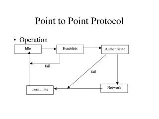
Modulation Bit Encoding Framing Error Detection Reliable Transmission Media Sharing (broadcast channels). Point-to-point links. Building Blocks. General-purpose computers (e.g., workstation) or special purpose hardware (switches/routers) Finite memory (limited buffer space)

E N D
Modulation Bit Encoding Framing Error Detection Reliable Transmission Media Sharing (broadcast channels) Point-to-point links
Building Blocks General-purpose computers (e.g., workstation) or special purpose hardware (switches/routers) Finite memory (limited buffer space) Connect to the network using a network adapter (aka Network Interface Card – NIC) Fast Processor, slow memory Slow I/O bus CPU Network Cache (T o network) adaptor I/O bus Memory
Links Local area network (within your building or campus) is usually built from: Copper Cable Unshielded Category 5 Twisted Pair (UTP) Thin-net co-ax Thick-net co-ax Optical Fiber Multimode optical fiber Single-mode optical fiber
UTP • Consists of four pairs of cables • Each pair transmits a signal • Pairs are “twisted” together, to minimize interference from/to other pairs and other cables
Thick-Net Co-ax • It has two conductors (the center core and the metallic shield) • It was designed to transmit high-frequency signals • An ordinary cable acts like an antenna, and high frequency signals radiate away from the wire (power loss) • To prevent this, one of the conductors is formed into a tube and encloses the other conductor. This confines the radio waves from the central conductor to the space inside the tube.
Thin-net Co-ax • Similar to thick-net, just thinner
glass core (the fiber) glas cladding plastic jacket optical fiber Links - Optical • Advantages of optical communication • Higher bandwidths • Superior attenuation properties • Immune from electromagnetic interference • No crosstalk between fibers • Thin, lightweight, and cheap (the fiber, not the optical-electrical interfaces)
core of single mode fiber ~1 wavelength thick = ~1 micron core of multimode fiber (same frequency; colors for clarity) O(100 microns) thick Links - Optical • Single mode • Lower attenuation (longer distances) • Lower dispersion (higher data rates) • Multimode fiber • Cheap to drive (LED’s) vs. lasers for single mode • Easier to terminate
Connecting to the network core (businesses and universities) • T1 is a high speed digital network (1.544 mbps) developed by AT&T in 1957. • The primary innovation of T1 was to introduce "digitized" voice • It later started being used to transmit digital data (Internet traffic)
Chart 1 - T1 Hierarchy Continued..
Carrier Optical Links • Optical Carrier (OC) transmission rates are a standardized set of specifications of transmission bandwidth for digital signals that can be carried on Synchronous Optical Networking (SONET) networks.[ • Transmission rates are defined by rate of the bitstream of the digital signal, and are designated as OC-n, with a bandwidth of n × 51.84 Mbit/s.
Last-Mile Links: Residential Access Service Bandwidth POTS 28.8–56 Kbps ISDN 64–128 Kbps DSL 128 Kbps – 100 Mbps CATV 1–40 Mbps FTTH (fiber to the home) 50Mbps – 1 Gbps Plain Old Telephone System (POTS) modem over 3KHz “voice” channel ISDN: digital modem over 3KHz channel xDSL/ADSL: Telephone company providing more bandwidth CATV: use the co-ax cable provided by the cable TV company
Sums of Sines and Cosines • All signals through a medium are electromagnetic waves. • Each signal can be decomposed into (represented as) an infinite sum of sines and cosines. • The more terms above are added, the closer the sum of sines and cosines becomes to the original signal.
Electromagnetic Spectrum • Each medium has a finite range of frequencies it can transmit
Square Waves What if we send our data (bits) as square waves? I.e., two voltages, high for 1 and low for 0? Problem: a square wave has an infinite number of frequency components. Thus many components will be lost and the signal distorted You also can’t do frequency division multiplexing (why?) 0 1 0 1 1
Modulation Encode the signal as a sine wave: A*cos(wt + p) A is the amplitude w is the frequency p is the phase Use modulation to encode the data, i.e., change the amplitude change the frequency change the phase change all of the above.
0 1 Amplitude modulation Frequency Modulation Phase Modulation
Baud vs Bit Rate Baud rate: number of transitions in the signal per second (e.g. how often can you change the amplitude?) Bit rate: how many binary bits can you transmit per second. Assume: 3 amplitudes, 3 frequencies and 2 phases I.e., 18 different “symbols” (combinations) if all of these can change at each transition. Then: bit rate = floor(log2(18)) * baud rate = 4* baud rate Two symbols go unused.
Baseband vs Broadband • Broadband • Only a range of the frequencies of the medium are available for transmission by the user • Data is modulated (frequency, shift, amplitude, etc) • This allows the data to only use a small range of frequencies of the medium • The remaining frequencies are used by other users. • Baseband • All the frequencies of the medium are available for transmission by the user • This allows the user to send a “square wave” • Square waves use all the frequencies of the medium • No problem, since no one else is also sharing the medium
Communication using a direct link – Issues Encoding: should we just pass the 1’s and 0’s as is? Synchronization: where does the data begin and where does it end? Bit synchronization Byte synchronization Frame synchronization Error Detection (and, possibly, correction) Medium Access Control (if not point to point) Signalling component Signal Node Adaptor Adaptor Node Bits
Physical Bits We will assume for simplicity : one bit per baud if we use modulation or a square wave if we use baseband Each signal encodes a physical bit (may be different from data bit, see later why) Thus, every time period of a baud encodes one bit. What if the signal does not change? (e.g., data has many consecutive 0’s? More on this later . . .
Bits are sent “as is” If bits do not change, then the signal does not change Problem: receiver keeps an average of the power level (e.g. in amplitude modulation) When a new bit is received, its signal value is compared to the average to determine its value. What if we have 10,000 consecutive zeroes (or 10,000 ones)? Non-Return to Zero (NRZ) Bits 0 0 1 0 1 1 1 1 0 1 0 0 0 0 1 0 NRZ
Clock Drift Consider sending 1000 consecutive one's: Sender and receiver's clocks aren't perfect: cannot run at exactly same speed. Let Ts = time duration of a sender’s bit as measured by “true” clock Tr = time duration of a receiver’s bit as measured by “true” clock If Ts 1.001 Tr (sender slower than receiver) then 1000*Ts 1001*Tr (receiver "sees" 1001 one's, rather than 1000) If Ts 0.999 Tr (sender faster than receiver) then 1000*Ts 999*Tr (receiver "sees" only 999 ones) Thus, this poses a big problem: long signals with no change cause more or less bits to be received.
Bit Synchronization Asynchronous Synchronize frequently send a short burst of bits (8-bits) followed by a synchronization sequence Mostly for low bandwidth inexpensive networks Synchronous Synchronize after every bit Transmit many bits at a time (thousands if desired) Uses codes that allow the clock to be recovered (self-synchronizing codes) Receiver derives sender’s clock from the received bits and adjusts itself accordingly.
Asynchronous Bit Synchronization The technique accomplishes bit and byte synchronization. Each byte transmitted is surrounded by a start bit (usually 1), one or more stop bits (usually 0's, must be different from start bit) When the sender is idle, it sends a continuous stream of zeroes. Periodically, the sender should send at least 10 bits of consecutive zeroes, in case the receiver loses track of which bit corresponds to the start bit. This technique is usually slow, because clock's not synchronized start-stop bit overhead.
Synchronous Transmission using Bit Encoding • Accomplishes bit synchronization at high speeds. • The whole frame is sent continuously without space between bytes. • The sender's and receiver's clock need to be running at exactly the same speed. • To do so, clocks are synchronized by encoding the sender's clock in the signal. • There are several encoding techniques.
Encodings Data Bits 0 0 1 0 1 1 1 1 0 1 0 0 0 0 1 0 Clock NRZ Manchester NRZI Manchester: XOR of NRZ and Clock (always a transition in the middle of a bit) NRZI: transition in the middle of bit indicates a one (does not solve the problem of consecutive zeroes.
Manchester More Detailed Let a "physical bit" be either a high (1) or a low (0) signal. Let a "data bit" be a real bit of information to be transferred. Each data bit is encoded as follows. data bit physical bits 0 01 1 10 There is always a signal transition in the middle of each data bit. Receiver uses these transitions to synchronize its clock to the sender's. This synchronization is what allows faster transmission speeds. 0 1 Data bits 1 0 1 0 0 0 0 1 1 0 0 1 Physical bits 1 1 1 0 Transitions in the middle of each data bit Clock signal of sender extracted from the bits
Recovery What if the receiver loses track? I.e., assume that the receiver loses track of which is the first physical bit of the two bits of each data bit. For example, if a physical bit received is a 0, is this the first physical bit of a 0 data bit, or is it the second physical bit of a 1 data bit? E.g. 01010101010101010101 . . . (physical bits) Is the above a sequence of 0 data bits or a sequence of 1 data bits?
Recover (continued) Notice the following data bit physical bits 00 0101 01 0110 10 1001 11 1010 Thus, two consecutive equal physical bits indicate a transition between data bits Receiver re-synchronizes when it receives two consecutive equal physical bits
4B/5B 4B/5B every 4 bits of data encoded in a 5-bit code 5-bit codes selected to have no more than one leading 0 and no more than two trailing 0s thus, never get more than three consecutive 0s resulting 5-bit codes are transmitted using NRZI achieves 80% efficiency! (vs. 50% of manchester)
Example of Used Encoding Approaches 4B/5B combined with NRZI used in FDDI (fiber token ring) 100 Mbit Ethernet Manchester encoding used in 10 Mbit Ethernet 8B/10B used in Gigabit Ethernet
Framing We have achieved bit-synchronization In the case of asynchronous, also byte synchronization Next, we need frame synchronization Typically implemented by the network adaptor (network card) A large sequence of bits needs to be delineated. This sequence is a message (a.k.a. frame) from the data link layer. Note: if we assume the sequence of bits is a sequence of bytes, then we also have byte synchronization.
Bit-Oriented Approaches Use a few bits to delineate the begin and end of a frame. We cover two approaches: Bit insertion (used in the HDLC data link protocol) Code violations (briefly)
Bit Insertion (a.k.a. bit stuffing) Assume the sender always (continuously) sends data bits. Why? to maintain bit synchronization using manchester encoding in a synchronous system. From now on we ignore physical bits, and consider only data bits. I.e., the physical bits received are decoded using manchester and the result is an infinite stream of data bits. But, what if the sender is "idle", i.e., which data bits are "idle" bits and which are "true" data bits? To determine this, one common technique is bit stuffing
Idleness vs. Data Idleness consists of k consecutive ones or more Sender and receiver must agree on k in advance, of course E.g., if k = 6, then 111111 is idleness, and so is 1111111, and also 11111111111. In general, the bit sequence looks like this, where x = data bit 11111110xxxxxxxxxxx011111111111110xxxxxxxxx01111111 idleness data bits idleness data bits idleness k consecutive one's should not appear in your data bits, i.e., inside xxxxxx. But what if your data does have k or more consecutive ones?
Inserting a "0" The sender "inserts" an additional zero every time there are (k-1) consecutive data bits equal to one. The receiver will remove this extra zero If your data has k-1 ones followed by a zero, you stillinsert a zero. For example, let k = 6, and you want to transmit as follows: data (ten ones) idleness 11111111110 idleness Then, your output is as follows: 1111111110 111110 111110 0 0111111111
More examples Next example, data idleness 11111011 idleness output: 1111111110 111110 011 01111111 Final example, data idleness 11111 idleness output: 11111110 111110 0111111111
Receiver Operation How does the receiver determine if a bit is data or idleness? One bits For a sequence of ones (surrounded by a zero on each side) the receiver simply counts the number of ones. If they are less than k, they are data bits, E.g.: input: 0111110 The ones have to be data, since #1's = 5 < 6 = k = 6 E.g.: input: 01111110 The ones have to be idleness, since #1's = 6 ≥ k = 6
Zero Bits Consider a zero bit, is it data or not? Must count the number of ones that occur before and after the zero. 0 111...1111 0 1111...1111 0 B ones z A ones Is the z bit (the zero with B ones before and A ones after) data or idleness? • If B k then z is not data, since the B bits are the idle flag • If B = k - 1 then z is not data, z is an inserted zero • If B < k-1 A k then z is not data, since z is the beginning of an idle • If B < k-1 A < k then (and only then) z is data
Remarks In practice, k = 6, hence 01111110 is a byte, and the pattern used is a little different: idleness flag data flag idleness 11111111111111 01111110 xxxxxxxxx 01111110 111111111111111 I.e., 01111110 is at the beginning and end of a message, to fill the idle space between messages, a sequence of at least 8 consecutive ones is used. Bit stuffing allows both character and frame synchronization (a frame is between idleness periods, each frame is a sequence of bytes)
Coding Violations Manchester allows only 01 and 10 for a 1 data bit and a 0 data bit Codes 00 and 11 are not used. You can transmit data this way (physical bits) 00 (data bits with manchester encoding) 11 Note that in doing so our earlier recovery scheme does not work What if we begin a frame with (physical bits) 0000 and end it with 1111? Will that work?
Initial Bit Synchronization in Synchronous Xmission • Assume we are doing Synchronous xmission (transmitting many bits, thousands, without stopping) • Assume, however, that the sender does not always transmit and the line is left with no signal (no voltage, nothing ...) • Consider the case of Ethernet, many nodes share the line • Thus, when idle, a node cannot xmit any signal otherwise it would interfere with other potential xmissions. • If no nodes xmit, the wire has no voltage • How do we perform our initial bit synchronization?
Preamble . . . idle . . . . . . idle . . . 01010101 . . . 01011 Data frame • Begin transmiting a “preamble”: a sequence of bits to aid in bit synchronization • In Ethernet, it is 7 bytes of 10101010 (“data” bits, NOT physical bits) • What do they look like in Manchester encoding? • Finish preamble with one special byte: 10101011 • Note: receiver does not count # of pairs 01 • Why? at the beginning, while synchronizing, it may miss a few • It is the “11” that determines the end of the preamble • The next bit is the first bit of the frame. preamble block of data bytes
Byte Oriented Approaches Assume you have a method that has achieved already byte-synchronization (e.g. the asynchronous bit synchronization we saw earlier, the output is a sequence of bytes) Thus, you receive as input an infinite sequence of bytes. Which is the first byte of the frame and which is the last? separate frames from each other in the input sequence of bytes
Character Insertion Approach(a.k.a. Sentinel Approach or Byte Stuffing) • Use special control characters to delineate the begin/end of the frame (and or sections of the frame) • What if the special control characters appear in the data? (Remember: users can xmit anything they want!) • Insert an “escape” character (often called DLE data link escape) before every special control character in the data. • What if “escape” exists in the data? • Send two “escapes” back to back • Two consecutive “escapes” are treated as a regular data byte whose value is equal to that of one “escape”
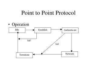
PPP Point-to-point protocol Used heavily in the internet in point-to-point links (especially modems) Flag: 01111110 Address field (constant value) 11111111 Control Field (constant value) 00000011 Protocol: which upper level protocol (e.g. IP) should receive data Data: the data itself of the upper level protocol CRC: error detection bits 16 8 8 8 8 32 Flag Flag Address data Control Protocol CRC