Download
1 / 17
170 likes | 177 Views
Lecture 27: Disks, Reliability, SSDs, Processors. Topics: HDDs, SSDs, RAID, Intel and IBM case studies Final exam stats: Highest 91, 18 scores of 82+ Every 15 th score: 82, 76, 71, 62, 52 Hardest question: Q2 (no score over 8/10) Q5: 2 perfect answers, 3 more nearly correct answers

E N D
Lecture 27: Disks, Reliability, SSDs, Processors • Topics: HDDs, SSDs, RAID, Intel and IBM case studies • Final exam stats: • Highest 91, 18 scores of 82+ • Every 15th score: 82, 76, 71, 62, 52 • Hardest question: Q2 (no score over 8/10) • Q5: 2 perfect answers, 3 more nearly correct answers • Q8: More than half of you solved it correctly
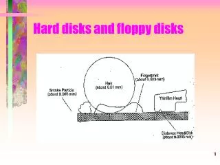
Magnetic Disks • A magnetic disk consists of 1-12 platters (metal or glass • disk covered with magnetic recording material on both • sides), with diameters between 1-3.5 inches • Each platter is comprised of concentric tracks (5-30K) and • each track is divided into sectors (100 – 500 per track, • each about 512 bytes) • A movable arm holds the read/write heads for each disk • surface and moves them all in tandem – a cylinder of data • is accessible at a time
Disk Latency • To read/write data, the arm has to be placed on the • correct track – this seek time usually takes 5 to 12 ms • on average – can take less if there is spatial locality • Rotational latency is the time taken to rotate the correct • sector under the head – average is typically more than • 2 ms (15,000 RPM) • Transfer time is the time taken to transfer a block of bits • out of the disk and is typically 3 – 65 MB/second • A disk controller maintains a disk cache (spatial locality • can be exploited) and sets up the transfer on the bus • (controller overhead)
RAID • Reliability and availability are important metrics for disks • RAID: redundant array of inexpensive (independent) disks • Redundancy can deal with one or more failures • Each sector of a disk records check information that allows • it to determine if the disk has an error or not (in other words, • redundancy already exists within a disk) • When the disk read flags an error, we turn elsewhere for • correct data
RAID 0 and RAID 1 • RAID 0 has no additional redundancy (misnomer) – it • uses an array of disks and stripes (interleaves) data • across the arrays to improve parallelism and throughput • RAID 1 mirrors or shadows every disk – every write • happens to two disks • Reads to the mirror may happen only when the primary • disk fails – or, you may try to read both together and the • quicker response is accepted • Expensive solution: high reliability at twice the cost
RAID 3 • Data is bit-interleaved across several disks and a separate • disk maintains parity information for a set of bits • For example: with 8 disks, bit 0 is in disk-0, bit 1 is in disk-1, • …, bit 7 is in disk-7; disk-8 maintains parity for all 8 bits • For any read, 8 disks must be accessed (as we usually • read more than a byte at a time) and for any write, 9 disks • must be accessed as parity has to be re-calculated • High throughput for a single request, low cost for • redundancy (overhead: 12.5%), low task-level parallelism
RAID 4 and RAID 5 • Data is block interleaved – this allows us to get all our • data from a single disk on a read – in case of a disk error, • read all 9 disks • Block interleaving reduces thruput for a single request (as • only a single disk drive is servicing the request), but • improves task-level parallelism as other disk drives are • free to service other requests • On a write, we access the disk that stores the data and the • parity disk – parity information can be updated simply by • checking if the new data differs from the old data
RAID 5 • If we have a single disk for parity, multiple writes can not • happen in parallel (as all writes must update parity info) • RAID 5 distributes the parity block to allow simultaneous • writes
RAID Summary • RAID 1-5 can tolerate a single fault – mirroring (RAID 1) • has a 100% overhead, while parity (RAID 3, 4, 5) has • modest overhead • Can tolerate multiple faults by having multiple check • functions – each additional check can cost an additional • disk (RAID 6) • RAID 6 and RAID 2 (memory-style ECC) are not • commercially employed
Error Correction in Main Memory • Typically, a 64-bit data word is augmented with an 8-bit • ECC word; requires more DRAM chips per rank and • wider bus; referred to as SECDED (single error correction • double error detection) • Chipkill correct: a system that can withstand complete • failure in one DRAM chip; requires significant overhead • in cost, energy
Flash Memory • Technology cost-effective enough that flash memory can • now replace magnetic disks on laptops (also known as • solid-state disks – SSD) • Non-volatile, fast read times (15 MB/sec) (slower than • DRAM), a write requires an entire block to be erased • first (about 100K erases are possible) (block sizes can • be 16-512KB)
Case Study I: Intel Core Architecture • Single-thread execution is still considered important • out-of-order execution and speculation very much alive • initial processors will have few heavy-weight cores • To reduce power consumption, the Core architecture (14 • pipeline stages) is closer to the Pentium M (12 stages) • than the P4 (30 stages) • Many transistors invested in a large branch predictor to • reduce wasted work (power) • Similarly, SMT is also not guaranteed for all incarnations • of the Core architecture (SMT makes a hotspot hotter)
Case Study II: Intel Nehalem • Quad core, each with 2 SMT threads • ROB of 96 in Core 2 has been increased to 128 in Nehalem; • ROB dynamically allocated across threads • Lots of power modes; in-built power control unit • 32KB I&D L1 caches, 10-cycle 256KB private L2 cache • per core, 8MB shared L3 cache (~40 cycles) • L1 dTLB 64/32 entries (page sizes of 4KB or 4MB), • 512-entry L2 TLB (small pages only)
DIMM DIMM DIMM DIMM DIMM DIMM Nehalem Memory Controller Organization MC1 MC2 MC3 MC1 MC2 MC3 Core 1 Core 2 Core 1 Core 2 Core 3 Core 4 Core 3 Core 4 Socket 1 Socket 2 QPI DIMM DIMM DIMM DIMM DIMM DIMM MC1 MC2 MC3 MC1 MC2 MC3 Core 1 Core 2 Core 1 Core 2 Core 3 Core 4 Core 3 Core 4 Socket 3 Socket 4
Case Study III: IBM Power7 • 8 cores, 4-way SMT, 45nm process, 1.2 B transistors, • ooo execution, 4.25 GHz • 2-cycle 32KB pvt L1s, 8-cycle 256KB pvt L2 • 32 MB shared L3 cache made of eDRAM • Nice article comparing Power7 and Sun’s Niagara3: • http://arstechnica.com/business/news/2010/02/two-billion-transistor-beasts-power7-and-niagara-3.ars
Advanced Course • Spr’11: CS 7810: Advanced Computer Architecture • Tu/Th 10:45am-12:05pm • Designing structures within a core • Cache coherence, TM, networks • Lots of memory topics • Major course project on evaluating original ideas with • simulators (often leads to publications) • No assignments • Take-home final
Title • Bullet