Download

1 / 51
630 likes | 1.2k Views
WELDING INSPECTION AND QUALITY CONTROL. Upon completion of this module you will be able to: Identify the different inspection methods used in non destructive testing. The uses and the limitations of the different inspection methods. Common methods used in NDE. Visual Inspection (VT)

E N D
WELDING INSPECTION AND QUALITY CONTROL Upon completion of this module you will be able to: • Identify the different inspection methods used in non destructive testing. • The uses and the limitations of the different inspection methods.
Common methods used in NDE • Visual Inspection (VT) • Magnetic Particle Inspection (MT) • Liquid (Dye) Penetrant Inspection (PT) • X-Ray inspection (RT) • Ultrasonic testing (UT) • Air or water pressure testing (LT)
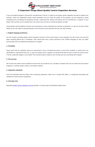
VISUAL INSPECTION – VISUAL TEST (VT) • What is Visual Inspection? • NDT process – non destructive testing is the original term used to identify a method of inspection that does not destroy a product usefulness. Current terms include nondestructive inspection (NDI) or nondestructive evaluation or examination (NDE) • Examination with the eye – therefore you are only able to DETECT SURFACE DISCONTINUITIES. • Most important and most extensively used NDE/NDI/NDT method (before any NDT or DT be applied.) II. Advantages A. Usually inexpensive - the majority of expense will be in the inspector’s wage. B. Equipment is small and inexpensive – there’s a lot of equipment to aid in visual inspection, but all small and inexpensive.
C. No powered required – this makes VT the most portable NDT process. D. Can avoid defects and costly repairs – by able to make intermittent inspection II. DISADVANTAGES • Requires training and experience –the inspector should be familiar with all the welding process. • Must have a good eyes – the AWS requires 20-40 natural or corrected distance acuity for a certified welding inspector. • May not detect internal defects – limited to surface discontinuities only, but it might give indication of substance indication. Then can be supplemented by some other NDT method. • No permanent records – the inspector must maintain a written log, supplemented by pictures, and tape recorded report. • Subject to human error – must spend adequate time to prevent errors.
IV. Five steps of Visual Inspection. • Inspection practice – establish a definite procedure to insure adequate and consistent coverage. • Inspection prior to welding • Inspection during welding • Inspection after welding • Marking and making repairs V. Equipment required. • Flashlight – used to remove shadows when an extension lamp can’t be used. • Magnifying glass – low power can be used with caution, if allowed by customer or code. • Protective lenses – pocket viewer with proper shade lens to watch the welding taking place. • Weld gage – are hand held measuring devices used to assist during welding and for final inspection.
E. Hammer and chisel – to remove spatter or slag from weld prior to inspection. F. Temperature Indicating Devices – some method must be used to determine the preheating, interpass and postheating temperatures. Pyrometer and tempelstick or crayons are commonly used. G. Magnet – a magnet can be used to help determine a materila type. • VI. Inspection Before Welding • Drawing – drawing are complete and accurate? • Position of welds – does the position called for correspond to the procedure or specification? In vertical is direction of travel correct? • Welding symbols – if they are used are they complete and accurate? • Welding procedure – is the procedure complete and accurate according to the code or specification?
E. Material • Did purchasing obtain the correct material such as base metal type and size. The correct electrode type size and the correct shielding gas type and grade. • Materials should be checked for defects. Base metal should be checked rust, mill, scale, laminations or delaminations. • Is the material preparation correct and according to procedure, such as angles and condition after preparation. F. Assembly • Inspect for proper fit up, as this will prevent discontinuities from occuring. • Jigs and fixtures will assure proper alignment. Make sure they are clean and free spatter and not damaged. • The tack welds are only short welds, but the quality must be the same as all other welds. The tack welds must be made with the same electrodes that are used for the rest of the welds.
4. Pre heat will be used to slow the cooling rate and prevent distortion. The pre heat could be used prior to tacking and / or prior to welding. G. Equipment • Inspect the equipment for any damaged such as damaged cables, damaged ground clamps, or electrode holders. Inspect the arc voltage and amperage meters making sure they are with in range. VII. Inspection DURING welding. • Electrodes – inspect for usage of proper electrodes, types, size and storage. Low hydrogen type must be stored in a stabilizing oven. • Root pass – the first layer or root pass is the most important and is particularly susceptible to cracking. Thicker material will crack and will require more pre heat. • Subsequent passes – inspection of successive layers is sometimes carried out with the assistance of workmanship
Standard. Check for contour or undercut as these are good places for slag to be trapped. Check for proper cleaning between passes as this can prevent slag entrapment. D. Crater formation – make sure crater are filled as this are areas where crack are easily formed. E. Weld size and sequence – are the weld size according to the print and is the layer and sequence according to the procedure? The use of various gages will determine this. VIII. Inspection After welding • The applicable code or standard – it will list acceptance standards They will generally cover the following areas; • Weld size – use gages to check conformance to prints • Contour and finish – is the contour convex or concave, and what was called for in print? Is finish smooth and free from surface irregularities. • Cracks – the code or standard will state if any is acceptable and what size.
4. Overlap – it is an indication of lack of fusion 5. Undercut – if allowed how much? 6. Spatter – what is excessive? IX. Making repairs A. When marking areas to be repaired the marking should be positive and clear. It should be a method that is understood by all involved, should be permanent enough to be evident after the repair has been made and inspected, and the marking must not damaged the part.
Visual Inspection (VT) • Fillet gauges measure • The “Legs”of the weld • Convexity • (weld rounded outward) • Concavity • (weld rounded inward) • Flatness
Liquid (Dye) Penetrant Inspection (PT) • Liquid penetrant inspection uses colored or fluorescent dye to check for surface flaws. • PT will not show sub-surface flaws. • PT can be used on both metallic and non metallic surfaces such as ceramic, glass, plastic, and metal. • PT dose not require the part to be Magnetized.
DYE PENETRANTS • These are an aid to visual inspection 1. Cleaner Solvent 2. Penetrant 3. Developer • Will only find surface defects • Use correct type • Process Principle – 6 steps • Surface preparation • Penetrant application • Excess penetrant removal • Developer application • Inspection / evaluation • Post cleaning
DYE PENETRANTS • Types • Red • Flouresant • CAUTION • Oil based • Water washable
II. Application: • Ferrous and non ferrous materials • Plastic and glass – ceramics-insulators-anything that is nonporous III. Advantages: • Low cost • Ease in application and interpretation – easy to apply and interpret result, discontinuities readily visible and portable. • Less training time for applicator – easy process to learn. IV. Limitations: • Detects discontinuities that is open to surface only • Can not be used on porous or absorbent materials V. Safety a. Ventilation – check for toxic fumes from testing materials. Check for volatility -explosive or fire flash points
b. Fire safety – the test material maybe non flammable but the propellant used with spray cans maybe extremely flammable. VI. Types: • Fluorescent (type A) – a dye that emits visible light rays when viewed under black light. 1. considered to be more sensitive than the visible type 2. must be viewed under ultraviolet (black light) in darkened overall lighting conditions. More expensive because of equipment required. Limited field use. B. Visible (type B) – a brilliantly colored dye that is highly visible under normal lighting conditions 1. Use normal lighting for inspection 2. considered to be less expensive. 3. Simplest to use. 4. Easy to use for field work 5. no electric power required
Dual sensitivity – works both fluorescent and visible. VII. Application • Follow Approved Procedure • Clean and dry the surface. - Solvent cleaner 2. Apply penetrant (brush, spray or dip) penetrant power comes capillary action 3. Penetration time -minimum dwell time is 5-20 minutes 3. Remove excess penetrant. - when using solvent type, put solvent on a cloth not on the part - excess penetrant will give false indications 4. Apply developer an allow developer dwell time per standard or specification. A “rule of thumb” developer dwell time is equal to one half penetrant dwell time. - developer will tend to make discontinuities appear larger.
6. Inspect and examine – true indications are caused by penetrant bleeding from actual discontinuities. 7. Clean if required – same as step 1. VII. Liquid Penetrant Comparator • Ideal temperature range of the material to be tested is 60 ⁰F –125⁰F. If the test must be done outside of this range, further qualification maybe required. • Test block – to establish acceptability limits of contamination and dilution to see if developer and penetrant are OK. 1. Plated panels – brass panels are plated with nickel and chromium are bent to produce cracks. 2. steel test blocks – annealed type 201 0r 302 stainless steel. Sandblasted on one side only with 100 mesh average size grit, gun held at 18” at 60 psi to achieve velvety finish.
3. aluminum test blocks – type 2024 by heating to 975F and quenched to form cracks. Used to check comparison for operating out of the normal temperature range. Used also to qualify penetrant if shelf is questionable. • Preparation for reuse – blocks should be cleaned with solvent to remove all penetrant from cracks and then heated to dry and also to drive out any remaining solvent. end
Magnetic Particle Inspection (MT) • Magnetic Particle Inspection (commonly referred to as Magnaflux testing) is only effective at checking for flaws located at or near the surface. • MT uses a metallic power or liquid along with strong magnetic field probes to locate flaws. (Particles will align along voids) • MT can only be used on materials that can be magnetized. It can not be used be used for nonmagnetic materials such as Austenitic Stainless steel and aluminum. Principle: An electric current is allowed to flow in or an electromagnet is applied to part of the specimen to cause magnetic flux to flow in the specimen.
SN SN SN If a defect exist in the surface layer, it blocks the flux flow, so the flux flow is directed around the defect while it partially leaks to the air. The leaking flux forms a pair of magnetic poles, S and N, on both sides of the defect.(as shown) SN SN SN SN SN SN SN SN SN N S Fig. A
Since the magnetic poles have larger attractive force than the surrounding material surface, magnetic particles are attracted by and adhere to the magnetic poles while attracting each other. As a result, a magnetic particle pattern wider than the defect is formed on the surface around the defect. Width of magnetic particle pattern Width of defect
To enable the formation o a proper magnetic particle pattern for defect indication, the orientation of the defect and magnetic field must be taken into account. Two methods of magnetizing the weld zone. • The YOKE method which uses an electromagnet • The PRODE method in which electrode are applied to the specimen to allow current to flow in the specimen. - not applicable to high tensile steel since it can form a short circuit between specimen and electrodes causing a defect resembling an arc strikes. - effective to detecting defects not exposed but existing near the surface. Two types of magnetic particles: • Fluorescent type • Non fluorescent type
Methods of particle application: • Wet method – magnetic particles are dispersed by suspension in water or kerosene and the suspension is applied to the specimen surface. • Dry method –magnetic particle are dispersed in the surface of the specimen.
MAGNETIC PARTICLE • Mainly for surface defects • Some sub surface defects can be found • Only ferrous metal
Ultrasonic testing (UT) • Ultrasonic testing (UT) is a method of determining the size and location of discontinuities within a component using high frequency sound waves. • Sound waves are sent through a transducer intothe material and the shift in time require for their return or echo is plotted. • Ultrasonic waves will not travel through air therefore flaws will alter the echo pattern.
ULTRA SONIC oscilloscope
Advantages: • Time to inspect – fast response / ability to inspect from one side. • B. Cost - $3,500.00 machine / $200.oo transducer • Portable with battery pack • Accuracy can locate small discontinuity Limitations: • Equipment • Operator • Standards • Reports and records
Radiographic Test (RT) • Radiographic Test is a NDT that can detect surface and internal discontinuities using electro magnetic radiation of short duration by means of either • 1. X-Ray • 2. Gamma Ray • It is a wave of energy that will pass through most materials and develop the negative image of what it passes through on film. Both of these methods are a danger to health 1. An X-Ray- Is electronically produced in a vacuum tube. 2. Gamma Ray-are emitted by the atomic decay. • Two Common Source of Gamma Rays. • Cobalt 60 • Iridium 192 • 3.FILM VIEWER • Pictures taken are viewed as negatives will only give flat image not in three dimensional darkened area must be used for viewing.
X-RAY VIEWER Pictures taken are viewed as negatives will only give flat image not in three dimensional darkened area must be used for viewing
Advantages: • A Radiograph ( X-Ray picture) is a permanent record of a weld used for quality inspection purposes • RT inspections can reveal flaws deep within a component • Limitations: • The necessity to have access to both sides of the part being radiographed • Unfavorable shape and orientation of some discontinuities. • Radiation Safety requirements for personal protection. • Tight Cracks, unless they are essentially normal to the radiation beam. • Shallow tight surface cracks in thick sections usually can not be detected at all, even when properly oriented. • Laminations are nearly impossible to detect because their orientation does not permit sufficient differences in the amount of radiation absorbed through the piece being examined to show the defect on film.
Air or water pressure testing (LEAK TEST) • Pressure testing or leak testing can be performed with either gasses or liquids. • Voids that allow gasses or liquids to escape from the component can be classified as gross (large) or fine leaks. • Extremely small gas leaks measured in PPM (parts per million) require a “Mass Spectrometer” to Sniff for tracer gases
APPLICATION OF A LOAD • Used to test pressure vessels • Pipe lines • The item for testing is filled with water or oil it is then pressurised using a pump • A safety valve is set 1.5 to 2 times below the working pressure.
PRESSURETEST Pressure Gauge Pump Test Specimen
Quiz time • True or False ? • Dye penetrate inspections can only be used on non magnetic material. • Answer: False
Quiz time • True or False ? • X-Rays can only be used to locate flaws at or near the surface of a weld. • Answer: False
Quiz time • True or False ? • Virtually all welds have flaws. • Answer: True
Quiz time • True or False ? • Magnetic particle testing can only detect flaws at or near the surface. • Answer: True
Quiz time • True or False ? • Magnet particle testing can only be done on materials that can be magnetized. • Answer: True
Quiz time • The letters NDE Mean ___________ ? A: nondestructive inspection B: nondestructive evaluation C: nondisruptive evaluation D: nondestructive examination
Quiz time • The method most often used to check for leaks as small as one part per million (PPM) from a gas line or cylinder is the _________ Method ? A: hydrostatic B: mass spectrometer C: soap suds bubble D: scleroscope