Download
1 / 23
250 likes | 577 Views
Chap 5. Dielectric and Insulators. 5. Dielectrics and Insulators. <PART I CAPACITIVE APPLICATIONS> • 5.3 THERMAL SHOCK RESISTANCE • 5.4 CAPACITORS 5.4.1 Capacitor characteristics 5.4.2 Non-ceramic capacitors 5.4.3 Ceramic capacitors.

E N D
5. Dielectrics and Insulators <PART I CAPACITIVE APPLICATIONS> • 5.3 THERMAL SHOCK RESISTANCE • 5.4 CAPACITORS 5.4.1 Capacitor characteristics 5.4.2 Non-ceramic capacitors 5.4.3 Ceramic capacitors
5.3 THERMAL SHOCK RESISTANCE • TSR은 전자ceramic의 구성과 응용면에서 중요한데 정확한 평가가 어렵다. • one being that a failure criterion which depends on the application has to be adopted. • real difficulties a useful guide to TSR is the quantity (thermal conductivity, strength, Young’s modulus, coefficient of linear expansion) 값은 ceramic에서 거의 상수( ) 그러므로 TSR을 결정하는 요인: , • but this is only a rough guide and the matter of TSR,like electric strength, is extremely complex.
5.4 CAPACITORS • Fulfill various function -Blocking -coupling -decoupljng -AC-DC separation -filtering -energy storage -blocking direct current but pass alternating current -charge storage capability : photoflash unit of a camera
5.4.1 Capacitor characteristics • Volume efficiency • : measure of the capacitance that can be accommodated in a • given size of capacitor. 평행판 capacitor의 면적 : A 전극간 거리 : h Volume efficiency volume efficiency는 비유전율에 비례, 유전체 두께의 제곱에 반비례.
5.4.1 Capacitor characteristics • Volume efficiency • But 는 (breakdown value)에 도달할 것이다. 두께를 무작정 줄일 수 없다. • Working voltage < normal breakdown voltage • maximum permissible energy density Used at high fields e e 2 2 CU E = 0 w r b h 2 2 V 2 • table 5.1(p.190): capacitor에 따른 volumetric efficiency 나타냄.
5.4.1 Capacitor characteristics (b)DCresistance Charged capacitor will discharge through its own resistance. : remaining charge, original charge Time constant of the capacitor Depend on the dielectric material • depend on dielectric except high working voltage(>1kV)
5.4.1 Capacitor characteristics (C) Equivalent parallel and series resistance • dissipation factor : DC leakage resistance , dielectric losses (lead, electrode resistances) 반비례, but depond on , temp. • the matter is more complex than appears at first
5.4.1 Capacitor characteristics (d) Resonance frequency • examine how the equivalent circuit for a typical capacitor respond to frequency Mica capacitor, assumed to be independent of frequency. << 1
5.4.1 Capacitor characteristics (d) Resonance frequency • increase decrease and approximates to • Resonance effect places an upper Limit on the freq. • above resonance the reactance of a capacitor is inductive( )
5.4.1 Capacitor characteristics (e) Breakdown and degradation • breakdown in a capacitor results in the replacement of a reactive insulating component by either a low-resistance short circuit or an open circuit. • breakdown field < intrinsic dielectric strength breakdown field : governed by the concentration of flaws(metallic inclusion, 기공, 가공되지 않은 표면 etc.) and the design of the electrode structure. •습기의 영향: 수증기에 낮은 유전율을 가지는 polymer로 싸거나 밀봉된 metal cans 안에 동봉하여 보호한다. • degradation은 ageing과 구별 ageing is due to the presence of ferroelectric domains and to a change in the mobility of the walls between them as time passes. • changes that occur in the properties : breakdown 확률의 증가와는 상관이 없고 오직 다른 특성들의 작은 변화들과 유전율의 감소를 제한한다.
5.4.2 non-ceramic capacitors (a) polymer-film capacitors • dielectric: 알루미늄 전극사이에 절연films (polymer,paper,both)을 끼워놓은 형태. •전극: 알루미늄 박 or 절연체에 직접 한 층을 증착시킨 형태 •알루미늄 cans이나 epoxy 수지로 동봉. ( 두께: 0.025 ) • 25% ~ 50%의 시장 점유율. • polystyrene capacitor: low (< ) 매우작다. •통신 장비로 frequency-selective circuit에 주로 사용 • power-factor correction, filter circuit 사용.
5.4.2 non-ceramic capacitors (b) Aluminium electrolytic capacitors •알루미늄 박으로 구성된 전극(순도: 99.99%, 50 ) 절연물 : porous paper •알루미늄 전해콘덴서는 paper 등에 전해액이 스며 들게 한 것을 알루미늄으로 감아 붙인 구조. •금속박의 표면에 전해산화피막( )을 만들고, 금속박을 양극,산화피막을 유전체, 전해액을 음극으로 한 콘덴서 •전자회로용 전원의 평활회로 바이어스를 가할 경우에 직류전압에 남아 있는 맥류를 제거하기 위해서 쓴다. •유전체층의 두께가 매우 얇아 소형·대용량인 장점이 있으나, 산화피막과 직렬로 전해액의 저항이 들어오므로 일반적으로 손실이 매우 크고 누설전류도 다른 콘덴서에 비해 많은 단점이 있다
5.4.2 non-ceramic capacitors (c) Tantalum electrolytic capacitors •전극에 tantalum 재료를 사용하고 있는 전해콘덴서. • tantalum powder를 소결( )하여 굳혔을 때에 나오는 빈틈을 이용하는 구조. •비교적 큰 용량 얻음. •온도 특성 우수.(온도의 변화에 따라 용량이 변화하는 것을 말하며 용량이 변화하지 않을수록 특성이 좋다) •알루미늄 전해 콘덴서에 비해 두루마리 구조가 아니므로 특성이 우수 •고정정도의 온도 특성이 필요한 회로, 주파수가 높은 회로 등에 사용 •알루미늄 전해콘덴서에서 발생하는 spike 형상의 전류가 나오지 않으므로 신호 파형을 중요시하는 아날로그 신호계에는 탄탈 콘덴서를 많이 사용
5.4.2 non-ceramic capacitors (d) Mica capacitors •운모(mica)를 유전체로 사용한 콘덴서. •운모는 온도계수가 작고 안정성이 우수하며, 주파수 특성도 양호하기 때문에 고주파에서의 공진회로나 필터회로 등에 사용. •절연내압도 우수하므로 고압회로에도 많이 사용 •단점: 용량이 그다지 크지 않고, 비싸다.
5.4.3 ceramic capacitors (a) Classes of dielectric Class I • low and medium –permittivity ceramics •비유전율( ): 15~ 500 • dielectric factor <0.003 • temperature coefficient : -2000 ~ +100 Class II • high –permittivity ceramics •비유전율( ) : 2000 ~ 20000 • dielectric factor <0.03 • class I에 비해 온도, 전계, 주파수에 민감 Class III •매우 큰 비 유전율을 갖음. • class II와 성질은 비슷하지만 working voltage(2~25V)이상 저항이 급감하여 사용 불가. •충전 용량이 크다.
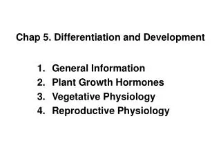
5.4.3 ceramic capacitors (b) Form and fabrication (i) Discs and tubes • discs can be formed by dry pressing calcined and milled powers containing some 5-10vol.% of an organic binder. They can be cut from extruded ribbon or band-cast tape. • tube are formed by extrusion. Advantage of being less fragile than flat pieces and are more suitable in some type of circuit assembly. after sintering , tubes are coated with silver. • lead and electrode inductance can be less in discs than in tubes so that discs have some advantage at higher frequencies. the two shapes are similar in volumetric efficiency since their bulk largely consists of the encapsulating resin. • disc and tubular shape are used for all classes of dielectric since they are lowest in cost.
5.4.3 ceramic capacitors (i) Discs and tubes
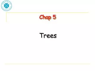
5.4.3 ceramic capacitors (ii) Multilayer capacitor •유전체 파우더를 tape casting등으로 수 마이크로 두께로 성형하여 그 위에 전극을 입힌 후 이것을 여러 층 적층하여 소성한 ceramic capacitor로 소형이지만 대용량을 얻을 수 있다는게 특징. •적층을 하는 이유는 capacitance를 높이기 위해서는 면적을 넓히거나 극간을 좁혀야 하지만 한계가 있다. 적층을 하여 단위 부피 당 더 큰 capacitance를 얻음.
5.4.3 ceramic capacitors (ii) Multilayer capacitor •전극간 공간: 20 •총 치수: 에서 • Dielectric : class I or class II 사용 • Electrode 내부전극 외부전극: • Termination 세라믹과 전극을 연결 하는 기능. •일반적으로 three process the wet, the dry, the fugitive electrode. fig.5.12 제조과정.
5.4.3 ceramic capacitors (ii) Multilayer capacitor
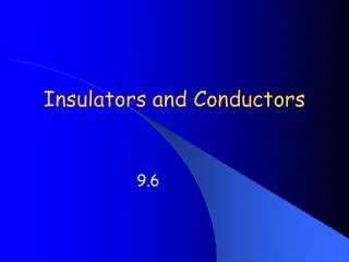
5.4.3 ceramic capacitors (iii) High-voltage and high-power capacitors • (a)와 같은 경우에는 전극의 끝부분에서 field의 세기가 커지게 된다. • Breakdown발생 (b)와 같이 전극의 끝을 구부려서 field의 세기를 조절한다. breakdown strength 증가 high-power capacitor 제작 가능. Fig.5.15(p.204)에서 high-power capacitor의 일반적인 형태.
5.4.3 ceramic capacitors (iii) High-voltage and high-power capacitors • the ceramic in a high-power capacitor is disc ,cylindrical, pot shaped. •절연체는 cavities로 부터 자유로워야 하고 기공이나 국부적으로 높은 전계가 걸리는 곳에서 플라즈마 방전을 피하기 위해서 일정한 density를 가져야 한다. •금속화 과정 3 단계. • class I dielectric 사용 • capacitance : 2pF~12nF peak voltage : 3kV rated power : 0.25~500kVA : 0.0005~0.001