Download
1 / 33
330 likes | 455 Views
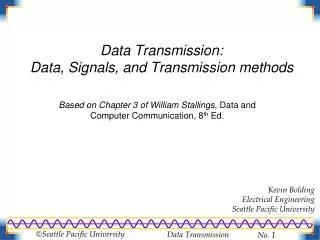
Understand computer networking basics from analog to digital signal methods, modulation techniques, bit stream to packets, error detection, framing, and encoding schemes.

E N D
From Signals to Packets Analog Signal “Digital” Signal 0 0 1 0 1 1 1 0 0 0 1 Bit Stream 0100010101011100101010101011101110000001111010101110101010101101011010111001 Packets Header/Body Header/Body Header/Body Packet Transmission Sender Receiver
M H H H H H H H H H t n l t t n l t n M M application transport network link physical M Link Layer: Implementation • Implemented in “adapter” • E.g., PCMCIA card, Ethernet card • Typically includes: RAM, DSP chips, host bus interface, and link interface network link physical data link protocol M frame phys. link adapter card
Outline • Physical media is analog • Modulation – signals to bits • Bit stream vs. packets • Framing – how to make packets • Corruption • Error detection & recovery
Modulation • Sender changes the nature of the signal in a way that the receiver can recognize. • Similar to radio: AM or FM • Digital transmission: encodes the values 0 or 1 in the signal. • It is also possible to encode multi-valued symbols • Amplitude modulation: change the strength of the signal, typically between on and off. • Sender and receiver agree on a “rate” • On means 1, Off means 0 • Similar: frequency or phase modulation. • Can also combine method modulation types.
Amplitude and FrequencyModulation 0 0 1 1 0 0 1 1 0 0 0 1 1 1 0 0 0 1 1 0 0 0 1 1 1 0 0 1 1 0 1 1 0 0 0 1
Assumptions • We use two discrete signals, high and low, to encode 0 and 1 • The transmission is synchronous, i.e., there is a clock used to sample the signal • In general, the duration of one bit is equal to one or more clock ticks
Clock Recovery • When to sample voltage? • Synchronized sender and receiver clocks • Need easily detectible event at both ends • Signal transitions help resync sender and receiver • Need frequent transitions to prevent clock skew • SONET XOR’s bit sequence to ensure frequent transitions
Encoding • Goal: Send bits from one node to another node on the same physical media • Problem: Specify a robust and efficient encoding scheme to achieve this goal
Encoding Schemes • Non Return to Zero (NRZ) • Non Return to Zero Inverted (NRZI) • Manchester Encoding • 4B/5B Encoding
Modulation • Non-Return to Zero (NRZ) • Used by Synchronous Optical Network (SONET) • 1=high signal, 0=low signal • Long sequence of same bit cause difficulty • DC bias hard to detect – low and high detected by difference from average voltage • Clock recovery difficult
Show the NRZ encoding for the following pattern Bits 1 0 0 1 1 1 1 1 0 0 0 1 0 0 0 1 clock NRZ
Modulation • Non-Return to Zero Inverted (NRZI) • 1=inversion of current value, 0=same value • No problem with string of 1’s • NRZ-like problem with string of 0’s
Show the NRZI encoding for the following pattern Bits 1 0 0 1 1 1 1 1 0 0 0 1 0 0 0 1 clock NRZI
Modulation • Manchester • Used by Ethernet • 1=low to high transition, 0=high to low transition • Transition for every bit simplifies clock recovery • Not very efficient • Doubles the number of transitions • Circuitry must run twice as fast
Modulation • 4b/5b • Used by FDDI • Uses 5bits to encode every 4bits • Encoding ensures no more than 3 consecutive 0’s • Uses NRZI to encode resulting sequence • 16 data values, 3 “special” illegal values, 6 “extra” values, 7 illegal values
Outline • Physical media is analog • Modulation – signals to bits • Bit stream vs. packets • Framing – how to make packets • Corruption • Error detection & recovery
Framing • Send ablockof bits (frames) between nodes connected on the same physical media • Length delimited • Beginning of frame has length • Single corrupt length can cause problems • Must have start of frame character to resynchronize • Resynchronization can fail if start of frame character is inside packets as well
Framing • Byte stuffing • Special start of frame byte (e.g. 0xFF) • Special escape byte value (e.g. 0xFE) • Values actually in text are replaced (e.g. 0xFF by 0xFEFF and 0xFE by 0xFEFE) • Worst case – can double the size of frame • Bit stuffing • Special bit sequence (0x01111110) • 0 bit stuffed after any 11111 sequence
Consistent Overhead Byte Stuffing • Run length encoding applied to byte stuffing • Encoding • Add implied 0 to end of frame • Each 0 is replaced with (number of bytes to next 0) + 1 • What if no 0 within 255 bytes? – 255 value indicates 254 bytes followed by no zero • Worst case – no 0’s in packet – 1/254 overhead • Possible optimization to encode series of 0’s
Encoding/Framing Summary • Encoding • Specify how bits are transmitted on physical media • Challenges – efficiency and robustness! • Framing • Specify how blocks of data are transmitted • Challenges • Deciding when a frame starts/ends • Differentiate between true frame delimiters and delimiters appearing in payload data
Outline • Physical media is analog • Modulation – signals to bits • Bit stream vs. packets • Framing – how to make packets • Corruption • Error detection & recovery
Error Detection • EDC= Error Detection and Correction bits (redundancy) • D = Data protected by error checking, may include header fields • Error detection not 100% reliable! • Protocol may miss some errors, but rarely • Larger EDC field yields better detection and correction
Parity Checking Single Bit Parity: Detect single bit errors
Error Detection - Checksum • Used by TCP, UDP, IP, etc.. • Ones complement sum of all words/shorts/bytes in packet • Simple to implement • Relatively weak detection • Easily tricked by typical loss patterns
Sender Treat segment contents as sequence of 16-bit integers Checksum: addition (1’s complement sum) of segment contents Sender puts checksum value into checksum field in header Receiver Compute checksum of received segment Check if computed checksum equals checksum field value: NO - error detected YES - no error detected. But maybe errors nonethless? Internet Checksum Goal: detect “errors” (e.g., flipped bits) in transmitted segment
Error Detection – Cyclic Redundancy Check (CRC) • Polynomial code • Treat packet bits a coefficients of n-bit polynomial • Choose r+1 bit generator polynomial (well known – chosen in advance) • Add r bits to packet such that message is divisible by generator polynomial • Better loss detection properties than checksums
Error Detection – CRC • View data bits, D, as a binary number • Choose r+1 bit pattern (generator), G • Goal: choose r CRC bits, R, such that • <D,R> exactly divisible by G (modulo 2) • Receiver knows G, divides <D,R> by G. If non-zero remainder: error detected! • Can detect all burst errors less than r+1 bits • Widely used in practice (ATM, HDCL)
CRC Example Want: D.2r XOR R = nG equivalently: D.2r = nG XOR R equivalently: if we divide D.2r by G, want reminder R D.2r G R = remainder[ ]
Error Recovery • Two forms of error recovery • Error Correcting Codes (ECC) • Automatic Repeat Request (ARQ) • ECC • Send extra redundant data to help repair losses • ARQ • Receiver sends acknowledgement (ACK) when it receives packet • Sender uses ACKs to identify and resend data that was lost
Error Recovery – Error Correcting Codes (ECC) Two Dimensional Bit Parity: Detect and correct single bit errors 0 0
Stop and Wait Simplest ARQ protocol Send a packet, stop and wait until acknowledgement arrives Sender Receiver Packet Time Timeout ACK
Recovering from Error Packet Packet Packet Timeout Timeout Timeout ACK ACK Time Packet Packet Packet ACK Timeout Timeout Timeout ACK ACK Early timeout Packet lost ACK lost