Download
1 / 28
280 likes | 420 Views
Status of the Tile-HCAL for the Detector at TESLA. 1. Actual project time planning 2. Groups involved 3. The milestones to the next PRC meeting 3. Actual R&D -- DESY-LPI -- DESY-H1 -- The minical array 4. E-flow studies -- The calorimeter prototype -- Testbeam at DESY

E N D
Status of the Tile-HCAL for the Detector at TESLA • 1.Actual project time planning • 2. Groups involved • 3. The milestones to the next PRC meeting • 3. Actual R&D • -- DESY-LPI • -- DESY-H1 • -- The minical array • 4. E-flow studies • -- The calorimeter prototype • -- Testbeam at DESY • -- Testbeams CERN, ...? • -- Collaboration with other groups II. ECFA-DESY LC workshop, St.Malo
Groups involved: • DESY-LPI, • tile-WLS fibre optimisation, • Photodetectors, simulation • DESY FLC activity • E.Devitsin, V,K., V.Kozlov, L.Popov, S.Potashov, A.Terkulov • V. Morgunov, simulation and reconstruction strategies • DESY-H1, • Photodet, preamps, ADC-RO, calibration, prototype simulation • V.Andreev, A. Fomenko, V.K., S.Reiche, P.Smirnov, Y.Soloviev • ITEP, Moscow • see presentation today • MEPHI, Moscow • see presentation today • Prague, • Univ. and Academy of Science • see presentation today • Imperial College London • and Birmingham • ADC-RO,together with ECAL • P. Daunkey et al. • Project time planing in 2002-2004: • R&D in 2002: • tile-fibre optimisation • signal RO • photodetectors • preamplifiers and shapers • ADC’s, FADC’’s • buffering and DAQ • studies with a ‘minical’ test array • technical design studies: • optimise the 1m3 prototype for HCAL • upgrade the TDR calorimeter design • simulation studies to optimise • the calorimeter structure • PRC meeting in November 2002 • 2003, prototype construction envisaged • 2004, prototype beam tests • and data collection • than presentation of realistic • E-flow reconstruction II. ECFA-DESY LC workshop, St.Malo
The milestones • The R&D program as reaction on demands of PRC: • agreed task list from 11.11.2001, DESY • 1. Period: 11.-12.2001 • -----------milestone: start minical test-array set up and - test operation at DESY, few channels • 2. Period: 1.-2.2002 • -----------milestone: LED stability monitoring, stable photo-detector operation possible, • -----------milestone: start cosmic test with minical, with increasing number of active tiles, • -----------milestone:finish construction design of 1m3-prototype (ITEP, Prague, DESY) • 3.Period: 3.-4.2002 • -----------milestone:optimal HCAL cell sizes defined from simulation (DESY), • -----------milestone: final results from homogeneity TF-system measurements and simulation • (Prague, ITEP), scintillator, WLS, reflector, clear RO fibres fixed. II. ECFA-DESY LC workshop, St.Malo
The milestones,2 4. Period: 5.-6.2002 -----------milestone:TF radiation hardness and ageing studies completed (Tashkent) -----------milestone: definition of final TF-RO plate geometry and RO fibre routing (ITEP) -----------milestone: operation of appropriate final Silicon Pixel PM's with preamps (MEPHI) -----------milestone: operation of all 64 PD's (CAMAC-RO) in minical (ITEP, DESY) 5. Period: 7.-8.2002 -----------milestone: build a prototype of multiplexing +ADC RO (similar to ECAL) (DESY, LPI, ITEP, IC, U-BIR) -----------milestone: minical beam-tests at DESY, 1-6 GeV e-test beam 6. Period: 9.-10.2002 -----------milestone: build a prototype of Mplx +ADC RO, (DESY, LPI, ITEP, IC, U-BIR) -----------milestone: run a complete minical, 64 channels with appropriate PD's and RO as envisaged for 1m3 PT (ITEP and DESY), MEPHI -----------milestone: beam tests with electrons, test: energy resolution, noise, linearity,..... (all institutes) -----------milestone:test minical in a 1.2 (4 T) magnetic field, needs inquiry II. ECFA-DESY LC workshop, St.Malo
R&D studies on the tile-WLS fibre system at DESY and LPI/Moscow Scintillator light yield R&D Scintillator : uniformity of RO Scintillator : ~6600 m2, costs! • Tile-WLS system: • optimal coupling, • light yield, • uniformity • >>>> 5x5 cm2, than: ...7x7....16x16cm2 tiles Reflector foil: mirror or diffraction, light yield Reflector foil: uniformity of RO Green WLS fibre: attenuation length WLS fibre: bending in small radius R&D by: DESY-H1-LPI , ITEP, Moscow, Prague WLS fibre: ageing, rad. hardness WLS fibre: fibre end mirroring clear RO fibre: attenuation length II. ECFA-DESY LC workshop, St.Malo
Find optimal WLS fibre Optimal WLS: -short abs. length for scintillation light -long atten. length of WLS shifted light II. ECFA-DESY LC workshop, St.Malo
Tile-reflector studies • So far studies with • aluminised mylar • white teflon foil • Tyvek paper (Papierunion) • best results with Tyvek • ----several layers needed • ----optimisation under way • >>>tests with super-reflector • (95-99%, 380 nm) • 3M special, • “3M Radiant Mirror Film” • 20% more light collected!!!! II. ECFA-DESY LC workshop, St.Malo
Scintillator/WLS fibre coupling Fibre end polished, open Tyvek coating of tile, air gap contact tile/WLS sensitive PM,number of photoelectrons from Gaussian fit to all individual N ph.e.contributions(poisson distrib.) Look for cheaper scintillator from Russia, with similar performance! II. ECFA-DESY LC workshop, St.Malo
Original concept of tile plate read out 1. layer original fibre RO concept as described in the TESLA-TDR. Problematic are the small scintillator tile sizes to be read out Study other possibilities II. ECFA-DESY LC workshop, St.Malo
Search for optimal WLS-Fibre arrangement • 10 different TF configurations studied • WLS fibre end polished, no reflector • air gap contact to tile • Tyvek reflector on tile • tile irradiated with • collimated Ru106 source, • simple current measurement for LY Ru106 source, s ~ 2cm II. ECFA-DESY LC workshop, St.Malo
Uniformity scan for optimal WLS-Fibre couplings 10 configurations studied: best LY: diagonal 1/4 c fibre, RO in groove best uniformity: straight fibre, RO outside tile All tiles: 5x5x0.5 cm3 s source =1.95 mm, II. ECFA-DESY LC workshop, St.Malo
Best coupling shape for WLS fibres? • Loops ph.e./tile ph./cell • 1 7.7 184 • 2 10.5 256 • 3 10.0 240 • unbent fibres: • along edge, no groove: 7.0 168 • along groove in centre 7.7 184 • diagonal fibre, groove: 10.5 256 • diagonal, minimal bend: 11.0 264 • Other criteria to use unbent fibres: • easy to insert, • less risk of damage • no bending stress, • > less ageing II. ECFA-DESY LC workshop, St.Malo
Photodetectors • Inside magnetic field: • HPD’s, expensive • Silicon photodiodes, low gain, noise, n.c.effects • APD’s, to study • Si-photomultipliers (Si-PM), see MEPHI presentation • Outside field: • single small photomultipliers, logistic problem, • Multi-anode photomultipliers (MA-PMT’s) • Some details: • ---APD’s: • gain of 100-500 possible, extended noise? • temperature stability, gain shift of 1-2% /°C • low capacities 10-15 pF possible, >> lower amplifier noise • tight packing in detector requires small sizes • Hamamatsu: >> 4x8 channel Si-APD array, S8550, study started in Prague, • 2 x 2 mm2 photo-cathode pixels, specimen >>> • common bias voltage, <500 V, gain 100-500 (?), lpeak~600nm, • >> work on integration with monolithic preamps, • in collaboration with • MPI Munich, Eckart Lorenz • ITEP, Y. Guilitski • Brookhaven, G. Woody ~1 x 2 cm2 II. ECFA-DESY LC workshop, St.Malo
Photodetectors • ---Si-PM’s: • Studies at MEPHI (Moscow), B. Dolgoshein, • See talk at International Conference on • “Advanced Technology and Particle Physics”, Como, Italy, Oct. 2001 • 100-4000 pixels/mm2 with common output, • pixel size is 15-50 mm, Cpixel ~100 fmF • each pixel consists of: • --drift region in inner electrical field (10-500 V/cm) • --Geiger region, ~0.7 mm, electrical field of 500.000 V/cm • gain 0.2..20*105 >> • --output signal is proportional to number of pixels fired: • S ~Npixel fired = m*(1-e-Nph*e/m) with: • M - total number of pixels, • Nph - number of photons, • e - photon detection efficiency. • --sensitive to single photons, • --problem is dark carrier rate (-40°C, ~200 kHz) >> • --first selected samples available Nov. 2002, • ---photomultipliers, • properties known, have to be small, compact and cheap! II. ECFA-DESY LC workshop, St.Malo
Photodetectors • ---multi-anode photomultipliers (MA-PMT’s) >>> • Hamamatsu, “Metal Channel Dynodes”, • types: • R5900-M16 >> H6568, 4x4 channels (4x4 mm2 each) or • R5900-M16 >> H7546, 8x8 channels (2x2 mm2 each) • New versions with less cross talk, • at DESY enough available to equip fully the ‘minical’, 64 channels • disadvantage: • sensitive to small magn. field variations, • dynamic range of MA-PMT’s is only a few times 102, • sensitive to fields > ~100 G, • light transport in ~7 m clear RO-fibres outside 4T field, • latt~ 10 m >> 50% amplitude loss, • gain uniformity between anodes: typ. 1.3 • cross talk in MA-PMT’s (~ 1-2%), • advantage: • easy access, • temp. stability, • small noise, • gain > 106 • >>>>> will be used for minical test array studies as first option II. ECFA-DESY LC workshop, St.Malo
The dynamic range of light signals: • MIP in 3 layer cell deposes ~70 MeV • maximal energy deposit ~ 15 GeV • If MIP counted in channel 10 • >>> 14.4 GeV >> channel 2048, • >>> dynamic signal range: 11 bit • 12 bit ADC’s would be excellent • overflow problem to study: • correction methods using neighboured cells, • non linear ADCs From V.Morgunovneeds to be referred to events II. ECFA-DESY LC workshop, St.Malo
monitoring gain of PD’s: • method A: • pulsed LED,light split and send to all • photodetectors, • a stable photodiode, • +/-1°C, dG/G < 1%o • monitors LED gain via signal peak position • method B: • pulsed LED,stable • gain from gaussian s of PM signal Calibration and monitoringof photodetectors • Cell calibration with MIP’s ! • ~250 000 cells, • many calibration events needed • off-line: • some days during shut down • online: • between bunch trains, cosmic muon • ~95% efficiency, • useful ~2*10-2 Hz, • >> 1728 events/day/cell • >> 2.4% calibration precision • in one calibration day! • in bunches (halo muons, endcaps only) • 10 halos/BC, >> 1.1*10-4/sec/cell • 14100 BC/sec , > 1.6 Hz/cell • >> few minutes calibration time needed II. ECFA-DESY LC workshop, St.Malo
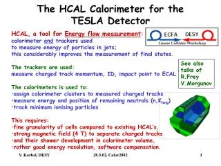
The layer structure of the HCAL • HCAL granularity to be optimised • for E-Flow reconstruction of jet energies, • ~angles • and jet-jet masses. • sandwich layers, lamination in: • 38 in barrel, 45 in end caps, • add. 4 in pole tips of end-caps • with scintillator tiles: ~ 800 000 tiles • sizes:~5x5......~16x16 cm2 • cells: ~ 160 000 cells • 9 (10) cell layers in barrel (end cap), • grouped from 3,3,3,4,4,4,5,5,7 • (3,3,3,4,4,4,5,5,7,7) s/w layers • cell volumes: • (0.22l)2 x0.36l .... (0.71l)2 x0.84l • (1.6 RMoliere)2 x 3.5 X0 ...(5 RMoliere)2 x 8 X0 • such a detailed structure to be studied in prototype II. ECFA-DESY LC workshop, St.Malo
A small pre-prototype : the „minical“-array • Assembled with up to • 27 scintillator layers: • 165 scintillator tiles of: • 5x5 cm2 >> 45 cells • 10x10 cm2 >> 8 cells • 20x20 cm2 >> 2 cells • read out by WLS fibres to • photo-detectors: • 16 small PM’s • 3x16 MA-PM’s, • 1x32 APD array • later: • Si-PM’s (MEPHI, Moscow) Track cambers? Cell structure Tile and S/w structure Aim of this device is study of: stability, ageing and calibration with MIP’s II. ECFA-DESY LC workshop, St.Malo
Beam tests with the „minical“-array • Beam at DESY, “Strahl 22” • reserved for • 2 weeks in July, set up, cosmics • 2 weeks in August, 1-6 GeV e- • later in this year: • test measurements in/between (?) solenoids • >>> APD’s or Si-PM’s as photodetectors needed! II. ECFA-DESY LC workshop, St.Malo
HCAL prototype for E-flow studies • Required volume ~ 1 m3 • ~ 800-1200 calorimeter cells • Fe-structure can accept • analogue • or digital HCAL 10 GeV pions 100 cm Leakage detector needed! 100 GeV pions II. ECFA-DESY LC workshop, St.Malo
Studies with the prototype beam tests:--1m3 structure made from Fe(ss) (or Brass?)--stack should be used for tile and digital HCAL studies--need electron, pion and proton test beam, muons for fast calibr?--different energies between 1-30 GeVperformance studies: --linearity, --energy calibration and energy resolution,--position resolution, --measure containment of showers, leakage (sides and back) >--software compensation (e/p) responseimprovementsimulation tests and reconstruction studies:--verify shower shapes from MC simulation, tune MC --energy flow studies, establishment of real performance:--overlay of individual measured beam particles to jets >>--with entrance coordinates and angles as indicated from MC--include cell size and nonuniformity, calibration precision, noise...>>>> reconstruct objects as Z, W, top, Higgsin these studies collaboration with interested US groups agreed II. ECFA-DESY LC workshop, St.Malo
Some first simulation results, reconstruction a la H1 /E ~ 0.395/E mean leakage/incoming pion • V.Andreev • pions in the 1m3 ss-prototype, • resolution ~ 0.395/E • considerable leakage deteriorates this resolution • tail catcher needed: • with 0.8 l dead Al coil • and realistic Fe structure • 1 cm2 cell structure, • RO of each layer >>>> 38 x 104 cells II. ECFA-DESY LC workshop, St.Malo
Realistic event representation Strong bending in the magnetic field of 4Tcharged particle showers are not vtx pointing t-tbar production, 800 GeV, several W jets II. ECFA-DESY LC workshop, St.Malo
Outcome of the meeting (27.3.02, Caltech, Pasadena, 19:30-21) , page 1 R. Frey, V. Korbel, S. Macgill, V. Morgunov, D. Strom, H. Videau, V.Zutshi agreement on closer future co-operation in calorimeter studies: 1. Invitation to the regular E- and HCAL meetings, especially members from ANL/ZEUS. Connection via Video-Conference, thus meetings will start at 14:00 MEZ. The next monthly HCAL meeting at DESY is scheduled for 6.6.2002. 2. We keep CALICE web page up to date with E- and HCAL meetings, pointers also to minutes and interesting transparencies of weekly DESY internal HCAL meetings. 3. Information on schedule for minical studies at the DESY test beam. First 2 weeks in July are planned for set-up of minical in test beam. Detailed studies are foreseen in the 2 last weeks of August for MIPs and electrons (1-6 GeV). 4. V.K. will contact Michael Hauschildt, the test beam co-ordinator at CERN and try to get information on availability of beams (1-30 GEV, hadrons, muons and electrons) in 2004, CERN PS. 5. For other alternative test beams we have to look for at Serpuchov, Brookhaven,….? 6. Discussions on specification of 1m3 HCAL prototype (absorber material, dimensions, tile sizes, equipped volume,..) and side leakage tagging and tail catcher requirements are under way. To optimise the prototype, simulation and reconstruction studies have started at DESY by the DESY-H1-PPI group. The US groups declared strong interest to contribute to such studies. 7. The Fe(ss)-HCAL stack is also foreseen for equipment with digital RO planes. 8. Study of the required tail catcher, structure and effective volume to fill (tile plates / digital planes). II. ECFA-DESY LC workshop, St.Malo
Outcome of the meeting (27.3.02, Caltech, Pasadena, 19:30-21) , page 2 9. Actual useable photodetectors, FE and RO electronics, all options have to be investigated for the prototype. A group of Imperial College, London has expressed strong interest to help with the design and implementation of the RO, starting from the ADC’s. So far DESY, ITEP, MEPHI, Prague are involved. 10. The beam test results will be used as input to - Shower size and energy resolution measurements for individual particles, - Leaking energy measurements, the improvement in resolution and reduction of missing energy tails, - Tune the software compensation a la H1 to improve further the energy measurement, - Realistic energy-flow studies with overlay and reconstruction of single particle clusters according to e.g. simulated W, Z, Higgs, t-tbar production....... 11. The effects of the magnetic field which changes significantly the charged track vectors in front of the calorimeter can be taken into account in a “realistic” energy flow simulation and reconstruction using measured prototype showers overlaid according to the simulated events in a cockeyed, non vertex pointing manner. 12. Aim is to find from such simulation and reconstruction studies all required beam test settings as: - Particle types and -energies, - Particle impact angles needed for overlays to jets and final states, - Number of particles to collect /data set. With these studies the useful prototype dimension, cell sizes and required volume fill (~4000 tiles combined to ~1000 electronic RO channels) and TC structure have to be optimised. Also we have to find out, which volume to fill with digital planes to draw a conclusive comparison. Probably, if 40 layers of digital RO will not be available at time for alternative test, as many tile layers as possible can be replaced with digital layers and consecutively shifted along the prototype depth. This can be studied in detail also! II. ECFA-DESY LC workshop, St.Malo
Summary • CDR >> TDR (2001) considerable improvement in concept • straight fibre RO, at least for small cells, instead loops, • >> ~25 ph.e. for calibration with PM for MIPs (~250 photons) • further work on further improvement in light yield, • lateral cell response uniformity seems ok (+/- 3-4%), • but needs confirmation by simulation studies • studies are underway for cell size optimisation • s/w compensation (~ size of elm. cluster) • E-flow measurement • economy, costs • minical-prototype is in operation, more channels soon • prototype tests at CERN envisaged for 2004 • wait for results from software prototype study group • how to implement realistic tail catcher? II. ECFA-DESY LC workshop, St.Malo
Minical Outlook Here we are 2002 Concept, design studies, R&D, prototype to be built for 2004 Approved, final concept 2005 ? design Detector ready for first e-e interactions: 2012 ? II. ECFA-DESY LC workshop, St.Malo