Download
1 / 1
50 likes | 224 Views
Black & Decker. Team: Jessica Dibelka, Mark Steimer, Laura Traub, Julianne Twomey. Sponsor: Steven Phillips, Sam Woods & Jason Leh Advisor: Dr. James Glancey. Results Analysis. Overview. FloWorks Modeling.

E N D
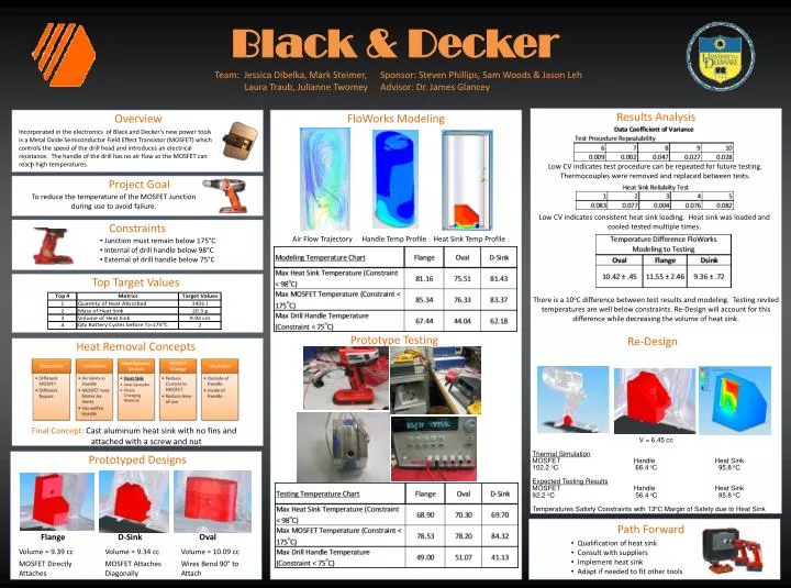
Black & Decker Team: Jessica Dibelka, Mark Steimer, Laura Traub, Julianne Twomey Sponsor: Steven Phillips, Sam Woods & Jason Leh Advisor: Dr. James Glancey Results Analysis Overview FloWorks Modeling Incorporated in the electronics of Black and Decker’s new power tools is a Metal Oxide Semiconductor Field Effect Transistor (MOSFET) which controls the speed of the drill head and introduces an electrical resistance. The handle of the drill has no air flow so the MOSFET can reach high temperatures. ( Low CV indicates test procedure can be repeated for future testing. Thermocouples were removed and replaced between tests. Project Goal To reduce the temperature of the MOSFET Junction during use to avoid failure. Low CV indicates consistent heat sink loading. Heat sink was loaded and cooled tested multiple times. Constraints Air Flow Trajectory Handle Temp Profile Heat Sink Temp Profile • Junction must remain below 175°C • Internal of drill handle below 98°C • External of drill handle below 75°C Top Target Values There is a 10oC difference between test results and modeling. Testing reviled temperatures are well below constraints. Re-Design will account for this difference while decreasing the volume of heat sink. Prototype Testing Re-Design Heat Removal Concepts Final Concept: Cast aluminum heat sink with no fins and attached with a screw and nut V = 6.45 cc Thermal Simulation MOSFET Handle Heat Sink 102.2 oC 66.4 oC 95.8 oC Expected Testing Results MOSFET Handle Heat Sink 92.2 oC 56.4 oC 85.8 oC Temperatures Satisfy Constraints with 13oC Margin of Safety due to Heat Sink Prototyped Designs Path Forward Flange D-Sink Oval • Qualification of heat sink • Consult with suppliers • Implement heat sink • Adapt if needed to fit other tools Volume = 9.39 cc MOSFET Directly Attaches Volume = 9.34 cc MOSFET Attaches Diagonally Volume = 10.09 cc Wires Bend 90° to Attach