Download
1 / 40
400 likes | 606 Views
Intuitive Kinematics – Converting Between Forward and Reverse Definitions of Space. Lecture Series 2 ME 4135 R. R. Lindeke. Intuitive Kinematics for Robot Manipulators. Defining the concept of the Kinematic Solution Finding Kinematic Solutions for POSITIONAL issues (only!)

E N D
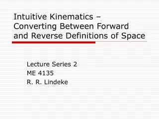
Intuitive Kinematics – Converting Between Forward and Reverse Definitions of Space Lecture Series 2 ME 4135 R. R. Lindeke
Intuitive Kinematics for Robot Manipulators • Defining the concept of the Kinematic Solution • Finding Kinematic Solutions for POSITIONAL issues (only!) • Cartesian Manipulators • Cylindrical Manipulators • Spherical Manipulators • Articulating Manipulators • SCARA and Other Redundant Manipulators
Intuitive Kinematics for Robot Manipulators • Forward Kinematic Solutions: • Given the settings on each Joint (q1, q2, ,qi) of the manipulator … • Determine the End Position (Xe,Ye, Ze)base achieved for the given structural size • Inverse Kinematic Solutions: • Given Structural Size and an End (or Target) Position (Xe,Ye, Ze)base … • Determine the values for each Joint (q1, q2, ,qi) that can place the Manipulator there • But, Note, this solution MAY NOT BE UNIQUE!
Cantilevered Cartesian Robot Z0 J2 J3 Y0 P-P-P Configuration X0 J1
Gantry Cartesian Robot P-P-P Configuration X0 Y0 Z0 J3 J2 J1
FKS & IKS for a Cartesian Device • In the Forward Sense: On the Gantry • J1 was at 435 cm • J2 was at 283 cm • J3 was at 199 cm • and there is a collapse lengthof 75, 50, & 50 cm respectively • Where is the End in the ‘Null (base) Space’?
FKS -- Cartesian • Xe is J1 + Cl1 = 435 + 75 = 510 • Ye is 283 + 50 = 333 • Ze is 199 + 50 = 249 • Exercise Care in the ordering of the Joints as they relate to the Base Frame definition of Space!!!
Doing the IKS • Given you want the End Position of: • (510, 333, 249) and the Collapse Lengths are as seen above (75, 50, & 50 respectively) • J1 is in the X0 direction therefore, • J1 = 510 – 75 = 435 (as expected!) • Similarly for J2 & J3 (which are 283 and 199 respectively) – again as expected • Here because of the directions the Joint motions follow and how the Base Axes are defined: • J1 in the direction of X0; J2 in Y0; J3 in Z0 – but be careful as we move deeper into robotics!
Cylindrical Robot Work Envelope P-R-P//R-P-P Configuration
Cylindrical Robot • Developing a FKS (model): • Given , Z & R • Compute End Position in terms of X0, Y0 and Z0 (Xe,Ye, Ze) Z0 R Y0 X0
IKS for Cylindrical Manipulator • Here, before we go on let me state this: • Sine and Cosine inverses lead to ambiguous angles (they repeat each semi-circle) since they are built from a ratio of a signed over an unsigned vector (Y/R or X/R ) • We MUSTuse inverse Tangent solutions to remove the ambiguity since tangent is built from a ratio of signed vectors (Y/X)
Cylindrical Robot • Doing IKS – given a value for: • X, Y and Z of End • Compute , Z and R Z0 R Y0 X0
Computing ATan2 Angles • Atan2(Xvalue,Yvalue) is a special form of Tan-1 but computed to retain quadrant identity • Consider the 4-cases of: X = 8 and Y = 12 • Atan2(8,12) = Tan-1(12/8) = 56.31 • This is a 1st Quadrant angle! • Atan2(-8,12) = 90 + Tan-1(8/12) = 90+ 33.69= 123.69 (alternatively it is 180 - Tan-1(12/8) = 180– 56.31 = 123.69) • This is a 2nd quadrant angle and not the -56.31 value that you find when computing Atan with your calculator! • Atan2(-8,-12) =180+ Tan-1(12/8) =180+ 56.31 = 236.31 • This is a 3rd quadrant angle! • Atan2(8,-12) = 270 + Tan-1(8/12) = 270+ 33.69= 303.69 (alternatively it is 360 - Tan-1(12/8) = 360– 56.31 = 303.69) • This is a 4th quadrant angle which is the same as your calculator gives you (-56.31)!
Spherical Robot Workspace R-R-P Configuration
Spherical Robot • Developing a FKS (model): • Given , & R • Compute Xe, Ye, & Ze R Z0 Y0 X0
Spherical Robot • Developing a IKS (model): • Given Xe, Ye, & Ze • Compute , & R R Z0 Y0 X0
2-Link Articulating Arm Manipulator • This Machine Rotates about Z0 Axis (1) • 2 is measured RELATVE to the base plane • 3 is measured RELATVE to L1 not the base plane • All Joint Angles are Right Hand Rule Based Z0 3 L2 2 L1 X0 Y0 1
2-Link Articulating Arm Manipulator Z0 3 L2 L1 X0 Y0 2 1
IKS 2-Link A. Arm • All angles defined as ATan2 (using target End Position & Link Lengths) • Requires Construction Lines!! • First Solve for 1 = ATan2(Xe, Ye) • Then the Tilt Angles (3 & 2) in reversed Order (as stated)! • Solution Indicates 2 acceptable configurations for the Arm: ‘Elbow UP’ and ‘Elbow DOWN’
IKS Q2 & Q3 q3 a q2
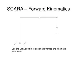
SCARA Manipulator – an over specified Planer Articulating Arm
FKS & IKS for this over specified Arm – Only 2 “State Equations” Exist for 3 Variables • In a Forward Sense solution is reasonable • In an Inverse sense the above statement indicates the existence of an infinite number of possible solutions • FKS: Given 1,2,3 find Xe and Ye • IKS: Given Xe and Ye (& L1, L2 and L3) find: 1,2,3
FKS 3-Link Planer A. Arm 3 y3 y2 q2 y1 1 x1 x2 x3
Focusing on the FKS • Project each link to the two axes (X & Y) • Xe is found by summing X-projected lengths of each link • Ye found by summing Y-projected lengths of the links • Example: • Link 1 to X: L1*Cos(1) • Link 1 to Y: L1*Sin(1)
FKS Continuing • X2 is projection of L2 – to the X axis therefore it requires what Projection Factor? • Sure, Cos(1+ 2) • Y2 is projection of L2 to the Y axis so it is equal to: L2* Sin(1+ 2) • Finally: • Xe = L1*Cos(1) + L2*Cos(1+ 2) + L3*Cos(1+ 2+ 3) • Ye =L1*Sin(1) + L2*Sin(1+ 2) + L3*Sin(1+ 2+ 3)
What about the IKS • It’s a 2 Step Process • Requires a Parameterization of one of the Joint Angles – This step will establish the acceptable limits of the solution space • The Parameterized Joint is said to set the BOUNDS for the solution space • We select Joint 1 as the one to be parameterized
3-Link Planer Arm IKS – Step 1 2’ Note: L2’ is the sum of L2 + L3 formed by freezing 3 at 0˚ 1
1 Is Solved as Above • It is the lower angle of a 2-link Articulating Arm • The 2 solutions found for 1 thus form the Upper and Lower Bounds for the solution space • Now pick one within the range • Using this angular value, “Transform” the solution space up Link L1 and ‘unfreeze’ 3
IKS Step 2:’Redefine’ Space at end of L1 and Re-apply 2-link method in the Transformed space 1,picked
Homework Assignment: • Complete the IKS solution for a 3-link planar articulating arm • Consider and complete the FKS and IKS solution for a “Planer” P-R-P device