Download
1 / 1
10 likes | 146 Views
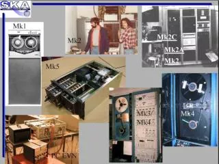
H-Maser. H-Maser. Storage* transport. Storage* transport. Data Storage*. Data Storage*. Link Design. Broadband VLBI Data Downlink of VSOP-2 Yusuke Kono 1 , Yasuhiro Murata 2 , Hisashi Hirabayashi 2 , Nanako Mochizuki 2 , Tomoaki Toda 2 , Kiyoaki Wajima 3

E N D
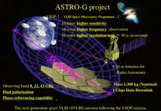
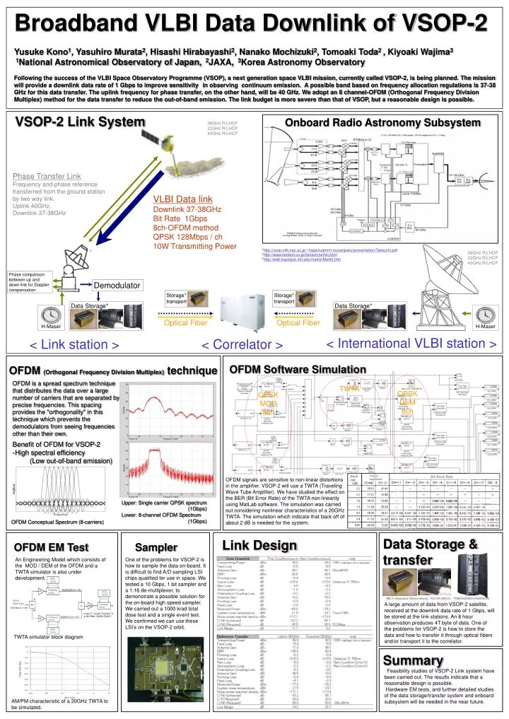
H-Maser H-Maser Storage* transport Storage* transport Data Storage* Data Storage* Link Design Broadband VLBI Data Downlink of VSOP-2 Yusuke Kono1, Yasuhiro Murata2, Hisashi Hirabayashi2, Nanako Mochizuki2, Tomoaki Toda2 , Kiyoaki Wajima3 1National Astronomical Observatory of Japan, 2JAXA, 3Korea Astronomy Observatory Following the success of the VLBI Space Observatory Programme (VSOP), a next generation space VLBI mission, currently called VSOP-2, is being planned. The mission will provide a downlink data rate of 1 Gbps to improve sensitivityin observing continuum emission. A possible band based on frequency allocation regulations is 37-38 GHz for this data transfer. The uplink frequency for phase transfer, on the other hand, will be 40 GHz. We adopt an 8 channel-OFDM (Orthogonal Frequency Division Multiplex) method for the data transfer to reduce the out-of-band emission. The link budget is more severe than that of VSOP, but a reasonable design is possible. VSOP-2 Link System Onboard Radio Astronomy Subsystem 08GHz R/LHCP 22GHz R/LHCP 43GHz R/LHCP Phase Transfer Link Frequency and phase reference transferred from the ground station by two way link. Uplink 40GHz, Downlink 37-38GHz VLBI Data link Downlink 37-38GHz Bit Rate 1Gbps 8ch-OFDM method QPSK 128Mbps / ch 10W Transmitting Power *http://vsop.mtk.nao.ac.jp/~nagai/submm-ryozanpaku/presentation/Takeuchi.pdf *http://www.fantech.co.jp/fantech/seihin.html *http://web.haystack.mit.edu/mark5/Mark5.htm 08GHz R/LHCP 22GHz R/LHCP 43GHz R/LHCP Phase comparison between up and down link for Doppler compensation Demodulator Optical Fiber Optical Fiber < International VLBI station > < Link station > < Correlator > OFDM Software Simulation OFDM (Orthogonal Frequency Division Multiplex) technique QPSK DEM 8ch QPSK MOD 8ch TWTA OFDM is a spread spectrum technique that distributes the data over a large number of carriers that are separated by precise frequencies. This spacing provides the "orthogonality" in this technique which prevents the demodulators from seeing frequencies other than their own. Benefit of OFDM for VSOP-2 -High spectral efficiency (Low out-of-band emission) OFDM signals are sensitive to non-linear distortions in the amplifier. VSOP-2 will use a TWTA (Traveling Wave Tube Amplifier). We have studied the effect on the BER (Bit Error Rate) of the TWTA non-linearity using MatLab software. The simulation was carried out considering nonlinear characteristics of a 20GHz TWTA. The simulation which indicate that back off of about 2 dB is needed for the system. Upper: Single carrier QPSK spectrum (1Gbps) Lower: 8-channel OFDM Spectrum (1Gbps) OFDM Conceptual Spectrum (8-carriers) Data Storage & transfer OFDM EM Test Sampler An Engineering Model which consists of the MOD / DEM of the OFDM and a TWTA simulator is also under development. One of the problems for VSOP-2 is how to sample the data on-board. It is difficult to find A/D sampling LSI chips qualified for use in space. We tested a 10 Gbps, 1 bit sampler and a 1:16 de-multiplexer, to demonstrate a possible solution for the on-board high speed sampler. We carried out a 1000 krad total dose test and a single event test. We confirmed we can use these LSI’s on the VSOP-2 orbit. *Mk-V (Haystack Observatory), *K5/VSI (NICT), *FANTAS8000 (FANTECH) A large amount of data from VSOP-2 satellite, received at the downlink data rate of 1 Gbps, will be stored at the link stations. An 8 hour observation produces 4T byte of data. One of the problems for VSOP-2 is how to store the data and how to transfer it through optical fibers and/or transport it to the correlator. TWTA simulator block diagram Summary Feasibility studies of VSOP-2 Link system have been carried out. The results indicate that a reasonable design is possible. Hardware EM tests, and further detailed studies of the data storage/transfer system and onboard subsystem will be needed in the near future. AM/PM characteristic of a 20GHz TWTA to be simulated.