Download

1 / 81
810 likes | 987 Views
The TTC system and Jitter in LHC experiments. PH-ESE seminar 18 December 2012. Sophie Baron. OUTLINE. Bunch Clock Origin From the Radio Frequency to the Bunch Clock The TTC system What is a good Bunch Clock ? Vocabulary – jitter , phase noise etc..

E N D
The TTC system and Jitter in LHC experiments PH-ESE seminar 18 December 2012 Sophie Baron
OUTLINE • BunchClockOrigin • From the Radio Frequency to the BunchClock • The TTC system • Whatis a good BunchClock? • Vocabulary – jitter, phase noise etc.. • Whois sensitive to what? • A good BunchClock in twowords • Measuring the clockquality • BunchClockmeasurement for the detectors • BunchClockmeasurement for the sub-systems • Conclusion • Lessonslearned PH-ESE seminar - 18 Dec 2012 - Sophie Baron
The Radio Frequency (RF) From Radio Frequency to Bunch Clock The Bunch Clock Clients The TTC system Bunch CLOCK ORIGIN PH-ESE seminar - 18 Dec 2012 - Sophie Baron
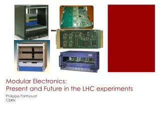
RF cavities in LHC (4 modules@point4, Echenevex) v v v v PH-ESE seminar - 18 Dec 2012 - Sophie Baron
The Radio Frequencyis not always the same protons • The Radio Frequency is not fixed: • it is a function of particle type and energy • It is ramping up at the beginning of each fill • it is modulated by beam characteristics and RF parameters • It is however extremely stable during flat top. Pb ions • 400.788860 MHz -> 400.789715 MHz (p in ring 1) • 400.784216 MHz -> 400.789639 MHz (Pb in ring 2) PH-ESE seminar - 18 Dec 2012 - Sophie Baron
Beamparameter Frequency program Synchro loop rephasing LowLevel loops processor Beam Radial Position VCXO 400MHz ÷10 Beam Phase (Bunch/RF Phase and Vt/RF Phase) 40MHz ÷3564 RF-Tx 11kHz 400MHz 11kHz Cavities Controller Beam monitoring system PH-ESE seminar - 18 Dec 2012 - Sophie Baron
LHC RF 400MHz Buckets 1 2 3 4 5 6 7 8 9 10 11 12 13 Bunch Beam LHC Bunch Clock 40MHz • The Bunch Clock is the frequency at which an observer sitting close to the ring could ‘see’ particles passing PH-ESE seminar - 18 Dec 2012 - Sophie Baron
Simplistic case: 2 bunches, 2 beams, 1 observer PH-ESE seminar - 18 Dec 2012 - Sophie Baron
Simplistic case: 2 bunches, 2 beams, 1 experiment, 1 fifo PH-ESE seminar - 18 Dec 2012 - Sophie Baron
In detectors, everything is happening synchronously to the Bunch Clock: • Collisions • Signal sampling for Analogue to Digital conversion • Time measurement • Trigger transmission • Data storage • Data reduction • Data transmission => The Bunch Clock has to be delivered EVERYWHERE, ANYTIME, and with a excellent QUALITY => This is one of the mandates of the TTC, and this is on what we will focus today PH-ESE seminar - 18 Dec 2012 - Sophie Baron
The Radio Frequency (RF) From the Radio Frequency to the Bunch Clock The Bunch Clock Clients The TTC system Bunch CLOCK ORIGIN PH-ESE seminar - 18 Dec 2012 - Sophie Baron
P5 P4 P2 CCR P8 TTC backbone TTC off-detector TTC on-detector PH-ESE seminar - 18 Dec 2012 - Sophie Baron
P5 P4 RF_Tx RF_Rx RF_Tx P2 CCR P8 TTC backbone RF_Rx RF2TTC TTCFanout TTC off-detector TTC on-detector PH-ESE seminar - 18 Dec 2012 - Sophie Baron
TTCex RF_Rx RF2TTC TTC Fanout TTCrx TTCrq QPLL TTCoc CTP LTP TTCvi PH-ESE seminar - 18 Dec 2012 - Sophie Baron
Vocabulary: Jitter & Co Who is sensitive to what? A good clock in 2 words WHAT IS A GOOD Bunch clock signal? PH-ESE seminar - 18 Dec 2012 - Sophie Baron
Time Domain measurements • Jitter types • Cycle to cycle jitter (cy2cy) • Periodjitter • Time IntervalErrorjitter • Skewjitter • Representation • Frequency Domain representation • Spectrum • Phase noise • Time and Frequencydomainrelationships • Jitterdecomposition PH-ESE seminar - 18 Dec 2012 - Sophie Baron
Time Domain measurements • Cycle-to-cyclejitter: • Short term variation in the clockperiodbetween adjacent clock cycles. • Contains the highestfrequency components of jitter. PiPi+1 Pi+2 Periodjitter: • Shortterm variation in the clockperiod over all measuredclock cycles, compared to the averageclockperiod. • Containsrelativelyhighfrequency components of jitter. • Do not mix withPeriodicjitter ΔPi=Pi-Pi+1 ΔPi+1= Pi+1-Pi+2 PH-ESE seminar - 18 Dec 2012 - Sophie Baron
Time Domain measurements • Skewjitter: Phase errorbetween the referenceclock and the measuredclock over all clockperiods. TIE(n)=T(n)-nT0 TIE(n+1)=T(n+1)-(n+1)T0 TIE jitter (Time IntervalError or accumulated/phase Jitter): • Actualdeviationfrom the idealclockperiod over all clockperiods. • Includesjitterat all modulation frequencies. • Analysisof itsProbabilityDensityFunction (PDF) givessubstantial information on the jitter sources. S(n+1)=T(n+1)-T0(n+1) S(n-1)=T(n-1)-T0(n-1) S(n+2)=T(n+2)-T0(n+2) S(n)=T(n)-T0(n) Wander: very slow variations < 10Hz. PH-ESE seminar - 18 Dec 2012 - Sophie Baron
σ= stddeviation = rmsjitter pkpkjitter PH-ESE seminar - 18 Dec 2012 - Sophie Baron
Frequencydomain: Spectrum and Phase Noise Ideal Oscillator : videal(t) = v0 sin 2π ƒct Real Oscillator : vreal(t) = (v0 +Δv(t)) sin(2π ƒct + ϕ(t)) Spectrum=frequency spectral density Phase Noise=phase spectral density Frequency domain of the signal Frequency domain of the phase noise S(ƒ) =|F[vreal(t)]|2 = |F[ (v0 + Δv(t))sin(2πƒt + ϕ(t))]|2 Sϕ(ƒϕ) =|F[ϕ(t)]|2= |ϕ(ƒϕ ~ )|2 PH-ESE seminar - 18 Dec 2012 - Sophie Baron
Time and Frequency Domain relationships • Getting RMS jitter out of phase noise plot (very close to TIE) [dBc/Hz] Phase Noise plot - discrete Offset Frequency (Hz) () () PH-ESE seminar - 18 Dec 2012 - Sophie Baron
Cycle to Cycle, Period and TIE jitter in frequencydomain PH-ESE seminar - 18 Dec 2012 - Sophie Baron
Wander: easy to visualize in frequencydomain PH-ESE seminar - 18 Dec 2012 - Sophie Baron
JITTER Gaussian and unbounded PDF, quantityisoften « rms » Usuallyperiodic or narrowband, the PDF isbounded, quantityisoften « pkpk » Random Jitter (RJ) Deterministic Jitter (DJ) Periodic Jitter (PJ) Data Dependent Jitter (DDJ) Not discussed in this talk - Impossible to detect on a simple clock signal. (Onlyvalid for clockrecovery out of a serial data link. Onlydetected by time domainanalysis) PH-ESE seminar - 18 Dec 2012 - Sophie Baron
Randomjitter sources • Caused by accumulation of a hugenumber of uncorrelatedprocessesthat have small magnitude • Random noise phenomena • Thermal noise, Shot noise, Pink noise, etc… • Occur in all semiconductors and components (PLLs, Oscillators, Tx, Rx etc…) • Typicalrepresentation of inducedjitter: Gaussian& unbounded PDF • Quantifiedby the Standard Deviation (rms) • Deterministicjitter sources • Causedby a comparativelysmallnumber of processesthatcanbecorrelatedand may have large amplitudes, • System & Data Dependentphenomena • Crosstalk, dispersion, impedancemismatch • Inter Symbol Interference (ISI), Duty-Cycle Distortion (DCD), Bit sequenceperiodicity • Typicallydetected as deviationof the PDF fromGaussianshape • Quantifiedby the pkpk value, as theyinduce a bounded phase deviation PH-ESE seminar - 18 Dec 2012 - Sophie Baron
Vocabulary: Jitter & Co Who is sensitive to what? A good clock in 2 words WHAT IS A GOOD Bunch clock signal? PH-ESE seminar - 18 Dec 2012 - Sophie Baron
Digital Systems: • Very sensitive to setup and hold time • basicallyrelated to pkpk cy2cy and periodjitter. • PLLs: • Track the slow variations of the clocks, and filter out the highfrequency components. • Can not deal withsudden jumps whichmayunlockthem. • pkpk cy2cy jitter • Wandercanalsobe a problemwhenitmeansfrequencydrifting out of the locking range. • ADCs: • Very sensitive to timing errors as jitterisdirectlyconvertedinto amplitude samplingerrors, and SNR. • Unregularlysamplingedgescandistort of the shape of digitized pulses. • This isthus more about pkpk cy2cy and periodjitterthan about TIE. PH-ESE seminar - 18 Dec 2012 - Sophie Baron
Serial Data Links: • Need to combine low Bit Error Rate (BER) and good ClockRecovery • BER isrelated to the quality of the clock • Transmitterisvery sensitive to anyclockjitter(because of clock multiplication). • On the channel, data jitteriscorrelated to Duty Cycle Distortionof the clock (DCD) • Receiver and CDR are highly sensitive to highfrequencyjitter • Quality of the ClockRecoveryis a trade off betweenlow BER (requireshighbandwidth PLL) and noise rejection (requiresnarrowbandwidth PLL) • Serial Data Links understandingrequiresTIEdecomposition and oftenfrequencydomainanalysis PH-ESE seminar - 18 Dec 2012 - Sophie Baron
Detectors - Event reconstruction over a huge system • 1000s of BunchClock destinations spread all over the detectors • LowSKEW JITTER betweenall clocksignals(fromevery branches of the distribution tree)to guarantychannel-to-channelconsistency • Stable phase betweenBunchClock and Beam • LowSKEW JITTER betweenBunchClock and Bunches over a fill • limitedWANDERduringbroadcast, in particular on long-haul transmission (between point4 and experiments) • DeterministicStatic Phase betweenbranches and top of the clocktreefromfill to fill and between power cycles PH-ESE seminar - 18 Dec 2012 - Sophie Baron
Vocabulary: Jitter & Co Who is sensitive to what? A good clock in 2 words WHAT IS A GOOD Bunch clock signal? PH-ESE seminar - 18 Dec 2012 - Sophie Baron
Detector cares about Stable Phase (slow variations or skew jitter versus reference) • Sub-systems care about Low Jitter (of Bunch Clock as such) PH-ESE seminar - 18 Dec 2012 - Sophie Baron
P5 P4 • Stable Phase • Beam Jitter: • Beam vs RF • Beam at experiments versus BC • Temperature drift P2 CCR P8 TTC backbone TTC off-detector TTC on-detector PH-ESE seminar - 18 Dec 2012 - Sophie Baron
Stable Phase • Beam Jitter: • Beam vs RF • Beam at experiments versus BC • Temperature drift • Determinism • BC at Front End Boards versus BC at Central Trigger • Channel skew jitter • BC at Front End Board X versus BC at Front End Board Y (channel to channel skew jitter) TTCex RF_Rx RF2TTC TTcrx CTP LTP TTCvi PH-ESE seminar - 18 Dec 2012 - Sophie Baron
Low Jitter • Cycle to cycle jitter • Period jitter • Overall jitter • Time Interval Error jitter • Phase Noise jitter PH-ESE seminar - 18 Dec 2012 - Sophie Baron
Phase Beam Jitter Temperature Drift Determinism Channel Skew Jitter Jitter Frequency Domain Analysis Time Domain Analysis Using Jitter Information Measuring the clock quality PH-ESE seminar - 18 Dec 2012 - Sophie Baron
P5 P4 P2 CCR P8 TTC backbone TTC off-detector TTC on-detector PH-ESE seminar - 18 Dec 2012 - Sophie Baron
Beam jitter versus RF • phase variations of the beam with respect to its reference (400MHz RF) • Maintained and monitored by the RF low level loops • 1374 bunches • Bunch position pkpk<5ps, rms<1.3ps Beamloadingeffectreflecting the bunch structure PH-ESE seminar - 18 Dec 2012 - Sophie Baron
Beam jitter versus experiment Bunch Clock • BPTX systems Use four screwed Electrostatic Button Electrodes to obtain Horizontal and Vertical position <50ps resolution by averaging First phase adjustmentjustbefore first collisions, ATLAS, nov 2009: Phase between 2 BPTX at ATLAS after fine phase with 2 beams just before collisions (90ps) Phase between 2 BPTX at ATLAS after cogging with 2 beams (900ps) Courtesy: Thilo Pauly Courtesy: Thilo Pauly PH-ESE seminar - 18 Dec 2012 - Sophie Baron
Analysis of BPTX data (example of CMS) 14-12-2009 Courtesy: Jan Troska PH-ESE seminar - 18 Dec 2012 - Sophie Baron
P5 P4 P2 CCR P8 TTC backbone TTC off-detector TTC on-detector PH-ESE seminar - 18 Dec 2012 - Sophie Baron
Up to 14km of burriedfiberfrom SR4 to ALICE, ATLAS, LHCb (1m deep) • The fibre length changes withtemperatureby 7ppm/degC • Measurements on a sparefiberfrom CCC to ATLAS and back (9km) • 8ns seasonal drift for 14km • VERY slow variation of the phase betweenbeam and clock (wander) • Need for regular calibration (usuallybeforeeachrun) with the help of BPTX and of the CORDE module for example • Keep in mindthat : the diurnal variation canbe150 ps= expect drift duringfills D. Gigi PH-ESE seminar - 18 Dec 2012 - Sophie Baron
TTCex RF_Rx RF2TTC TTcrx CTP LTP TTCvi PH-ESE seminar - 18 Dec 2012 - Sophie Baron
Determinism • Typical issue with commercial PLLs 1:M CLK IN CLK OUT VCO LPF Example: N=M=3 1:N CLK IN VCO out CLK OUT 3 possible phases at startup CLK OUT’ CLK OUT’’
Commercial PLL usual design GHz! VCO LPF 1:R 1xP1 1:M1 CLK IN CLK OUT1 1xP2 1:M2 CLK OUT2 1:N 1xPX 1:MX CLK OUTX
Solving phase determinism issues X X X Solution 1: • Used in • TTCex (discrete PLL with 160MHz VCO) • QPLL (custom ASIC made at CERN) • Extremely RARE in commercial PLL (no commercial interest) 1:M 1:M 1:M CLK IN CLK IN CLK IN CLK OUT CLK OUT CLK OUT VCO VCO VCO LPF LPF LPF CLK OUT 1:N 1:N 1:N Solution 3: • Found in some Commercial PLLs • Beware of METASTABILITY INTERNALLY SYNCHRONIZED RESET EXTERNAL RESET Solution 2: • Needs external phase monitoring • GBT implements this option • Can be provided by FPGA in counting rooms
Solution 3: Metastability issues 1:M CLK IN CLK OUT VCO LPF Sync Example of the CDCE62005 40MHz in VCXO out 1:M 1:N 1:M INTERNAL SYNC RESET
Solution 3: Metastabilityissues • Tests in climatic chamber
TTCex RF_Rx RF2TTC TTcrx CTP LTP TTCvi PH-ESE seminar - 18 Dec 2012 - Sophie Baron
Channel-to-channel skew • For a good event reconstruction • Time Of Flight (TOF) detectors • need less than 10ps rms between channels for particle mass identification • Reducing it: Trade off for the PLLs in the clocktree • Narrowbandwidth to clean the clock as much as possible • Widebandwidth to be sure PLLs do not drift toomuchfromeachother PH-ESE seminar - 18 Dec 2012 - Sophie Baron