Download
1 / 44
500 likes | 894 Views
CHAPTER OBJECTIVES. Review important principles of statics Use the principles to determine internal resultant loadings in a body Introduce concepts of normal and shear stress. Discuss applications of analysis and design of members subjected to an axial load or direct shear. CHAPTER OUTLINE.

E N D
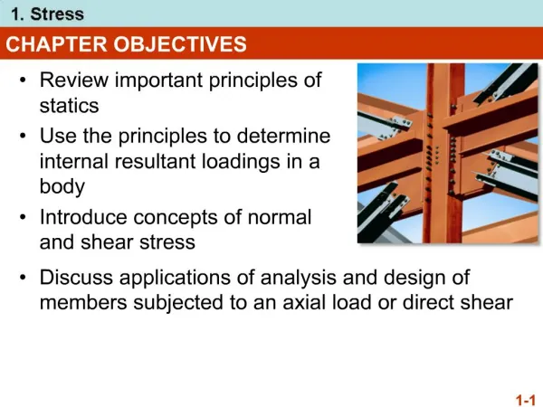
CHAPTER OBJECTIVES • Review important principles of statics • Use the principles to determine internal resultant loadings in a body • Introduce concepts of normal and shear stress Discuss applications of analysis and design of members subjected to an axial load or direct shear
CHAPTER OUTLINE • Introduction • Equilibrium of a deformable body • Stress • Average normal stress in an axially loaded bar • Average shear stress • Allowable stress • Design of simple connections
1.1 INTRODUCTION Solid Mechanics • A branch of mechanics • It studies the relationship of • External loads applied to a deformable body, and • The intensity of internal forces acting within the body • It is used to compute deformations of a body • Study body’s stability when external forces are applied to it
1.1 INTRODUCTION • Beginning of 17th century (Galileo) • Early 18th century (Saint-Venant, Poisson, Lamé and Navier) • In recent times, with advanced mathematical and computer techniques, more complex problems can be solved Historical development
1.2 EQUILIBRIUM OF A DEFORMABLE BODY • Surface forces • Area of contact • Concentrated force • Linear distributed force • CentroidC (or geometric center) • Body force (e.g., weight) External loads
1.2 EQUILIBRIUM OF A DEFORMABLE BODY Support reactions • for 2D problems
1.2 EQUILIBRIUM OF A DEFORMABLE BODY • balance of forces • balance of moments Equations of equilibrium ∑F = 0 ∑MO = 0 Two-Dimension: ΣFx= 0 ΣFy= 0 ΣMx= 0 Σ My= 0 Σ Mo= 0 Three-Dimension: ΣFx= 0 ΣFy= 0 Σ Fz= 0 ΣMx= 0 Σ My= 0 Σ Mz= 0 Σ Mo= 0
1.2 EQUILIBRIUM OF A DEFORMABLE BODY • For coplanar loadings (2-D): • Normal force, N • Shear force, V • Bending moment, M Internal resultant loadings
1.2 EQUILIBRIUM OF A DEFORMABLE BODY • For coplanar loadings: • Apply Fx= 0 to solve forN • Apply Fy= 0to solve for V • Apply MO = 0 to solve for Mo
1.3 STRESS Concept of stress • To obtain distribution of force acting over a sectioned area • Assumptions of material: • It is continuous (uniform distribution of matter) • It is cohesive (all portions are connected together)
1.3 STRESS Fig.(a) : A body is subjected to 4-forces and it is in equilibrium Fig.(b) : Method of Section. Internal force distribution acting on the exposed imaginary section.
ΔFz ΔA lim ΔA →0 σz = 1.3 STRESS Consider ΔA in figure above Small finite force, ΔF acts on ΔA As ΔA → 0, ΔF → 0 But stress (ΔF/ ΔA) → finite limit (∞) Normal Stress, s : The intensity of force, or force per unit area, acting normal to DA.
ΔFz ΔA lim ΔA →0 σz = 1.3 STRESS Normal stress • Intensity of force, or force per unit area, acting normal to ΔA • Symbol used for normal stress, is σ (sigma) Tensile stress: normal force “pulls” or “stretches” the area element ΔA Compressive stress: normal force “pushes” or “compresses” the area element ΔA
ΔFx ΔA lim ΔA→0 τzx = ΔFy ΔA lim ΔA →0 τzy = 1.3 STRESS Shear stress • Intensity of force, or force per unit area, acting tangent to ΔA • Symbol used for normal stress is (tau)
1.3 STRESS Stress Components : sz , tzx , tzy sy , tyx , tyz sx , txy , txz
1.3 STRESS General state of stress • Figure shows the state of stress acting around a chosen point in a body Units (SI system) Newtons per square meter (N/m2) or a pascal (1 Pa = 1 N/m2) 1 kPa= 103 N/m2 (kilo-pascal) 1 MPa= 106 N/m2 (mega-pascal) 1 GPa= 109 N/m2 (giga-pascal)
1.4 AVERAGE NORMAL STRESS IN AXIALLY LOADED BAR Examples of axially loaded bar • Usually long and slender structural members • Truss members, hangers, bolts, etc. • Prismatic means all the cross sections are the same
1.4 AVERAGE NORMAL STRESS IN AXIALLY LOADED BAR Assumptions • Uniform deformation: Bar remains straight before and after load is applied, and cross section remains flat or plane during deformation • In order to get uniform deformation, force P be applied along centroidal axis of cross section
1.4 AVERAGE NORMAL STRESS IN AXIALLY LOADED BAR Compression Tension P A P A σ = σ =
EXAMPLE 1-1 Bar width = 35 mm, thickness = 10 mm Determine maximum average normal stress in bar when subjected to loading shown.
PCD B C D A EXAMPLE 1-1 Internal loading PAB = 12 kN PBC = 30 kN PCD = 22 kN Normal force diagram By inspection, largest loading segment is BC, where PBC = 30 kN
PBC = 30 kN PBC A 30(103) N (0.035 m)(0.010 m) =85.7 MPa σBC = = EXAMPLE 1-1 Average maximum normal stress
EXAMPLE 1-2 The 200 N ( 20 kg) lamp is supported by two steel rods connected by a ring at A. Determine which rod is subjected to the greater average normal stress and compute its value. Take q = 60o. The diameter of each rod is given in the figure.
y FAC FAB 60o 60o x W EXAMPLE 1-2 Equation of equilibrium +Fx = 0, FACcos60o – FABsin60o = 0 +Fy = 0, FACsin60o + FABcos60o – W = 0 The 2 equations yield FAB = 100 N FAC = 173.2 N
y FAC FAB 60o 60o x W EXAMPLE 1-2 Average normal stress AAB = ¼ (12)2 mm2 = 113.1 mm2 AAC = ¼ (10)2 mm2 = 78.54 mm2 Substituting the appropriate values, we have sAB = 0.884 N/mm2 = 0.884 MPa sAC = 2.205 N/mm2 = 2.204 MPa The greater normal stress is in rod AC.
1.5 AVERAGE SHEAR STRESS • Shear stress is the stress component that act in the plane of the sectioned area. • Consider a force F acting to the bar • For rigid supports, and F is large enough, bar will deform and fail along the planes identified by AB and CD • Free-body diagram indicates that shear force, V = F/2 be applied at both sections to ensure equilibrium
V A τavg= 1.5 AVERAGE SHEAR STRESS Average shear stress over each section is: τavg = average shear stress at section, assumed to be the same at each point on the section V = internal resultant shear force at section determined from equations of equilibrium A = area of section
1.5 AVERAGE SHEAR STRESS • Case discussed above is example of simple or direct shear • Caused by the direct action of applied load F • Occurs in various types of simple connections, e.g., bolts, pins, welded material
1.5 AVERAGE SHEAR STRESS Single shear • Steel and wood joints shown above are examples of single-shear connections, also known as lap joints. • Since we assume members are thin, there are no moments caused by F
1.5 AVERAGE SHEAR STRESS Single shear • For equilibrium, cross-sectional area of bolt and bonding surface between the two members are subjected to single shear force, V = F • The average shear stress equation can be applied to determine average shear stress acting on colored section in (d).
Bolt F F Shear area 1.5 AVERAGE SHEAR STRESS The bolt is undergoing shear stress d = bolt diameter
1.5 AVERAGE SHEAR STRESS Double shear • The joints shown below are examples of double-shear connections, often called double lap joints. • For equilibrium, cross-sectional area of bolt and bonding surface between two members subjected to double shear force, V = F/2 • Apply average shear stress equation to determine average shear stress acting on colored section in (d).
Bolt F/2 F F/2 Shear area 1.5 AVERAGE SHEAR STRESS The bolt is undergoing shear stress: d = bolt diameter
Bolt Bolt F F/2 F F F/2 Single shear double shear 1.5 AVERAGE SHEAR STRESS Which one stronger ?? WHY ?? Smaller shear stress !!
Ffail Fallow F.S. = 1.6 ALLOWABLE STRESS • When designing a structural member or mechanical element, the stress in it must be restricted to safe level • Choose an allowable load that is less than the load the member can fully support • One method used is the factor of safety (F.S.)
σfail σallow τfail τallow F.S. = F.S. = 1.6 ALLOWABLE STRESS • If load applied is linearly related to stress developed within member, then F.S. can also be expressed as: In all the equations, F.S. is chosen to be greater than 1, to avoid potential for failure Specific values will depend on types of material used and its intended purpose
P σallow A = V τallow A = 1.7DESIGN OF SIMPLE CONNECTIONS • To determine area of section subjected to a normal force, use To determine area of section subjected to a shear force, use
A A A C C C 5 5 5 6 kN 6 kN 6 kN 3 3 3 4 4 4 A A A B B B B B B 2 m 2 m 2 m 1 m 1 m 1 m EXAMPLE 1-3 The two members pinned together at B. If the pins have an allowable shear stress of τallow = 90 MPa, and allowable tensile stress of rod CB is (σt)allow = 115 MPa Determine to nearest mm the smallest diameter of pins A and B and the diameter of rod CB necessary to support the load.
Ax Bx Ay By + + ∑MA = 0; + ∑Fx = 0; ∑Fy = 0; EXAMPLE 1-3 Draw free-body diagram of member AB: Reaction forces: By = 4 kN Ay = 2 kN Ax = Bx
C B By 5 3 4 Bx EXAMPLE 1-3 BComponents : By = 4 kN = B (3/5) Bx = B (4/5) We getBx = 5.32 kN Resultant reaction force: B= 6.67 kN
B = 6.67 kN Ay = 2 kN A Ax = 5.32 kN = 5.68 kN EXAMPLE 1-3 Resultant reaction force:
A = 5.68 kN VA VA EXAMPLE 1-3 Diameter of pin A (double shear): Shear force at pin A : VA = A/2 = 2.84 kN VA tallow 2.84 kN 90 103kPa AA = = = 31.56 10−6 m2 AA= (dA2/4) dA = 6.3 mm Choose a size larger to nearest millimeter: dA = 7 mm
B= 6.67 N VB Choose a size larger to nearest millimeter: dB = 10 mm EXAMPLE 1-3 Diameter of pin B(single shear): Shear force at pin B : VB = B = 6.67 kN Diameter of pin B : VB tallow 6.67 kN 90 103kPa AB = = 74.11 10−6 m2 = dB = 9.7 mm AB= (dB2/4)
C B Choose a size larger to nearest millimeter: dBC = 9 mm EXAMPLE 1-3 Diameter of rod BC: (The analysis is based on the normal stress) B (σt)allow 6.67 kN 115 103kPa = (dBC2/4) ABC = = 58 10−6 m2 = dBC= 8.59 mm