Download
1 / 53
530 likes | 673 Views
2. Advanced Medium Access Control Protocols. 2.1 Traditional CSMA/CD 2.2 The 802.11 MAC Protocol for Wireless LANs. What is a LAN?. Definition A LAN ( Local Area Network) is a network for the bit-serial transmission of data between independent peer stations .

E N D
2. Advanced Medium Access ControlProtocols • 2.1 Traditional CSMA/CD • 2.2 The 802.11 MAC Protocol for Wireless LANs
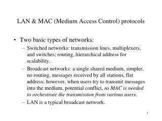
What is a LAN? • Definition • A LAN (Local Area Network) is a networkforthe bit-serial transmissionofdatabetweenindependentpeerstations. • Itisusuallyunderthe legal controlof a singleuser (singleenterprise) andisusually limited totheuser‘spremises.
Characteristics of a Local Area Network • High transmissionspeed(10 - 1000 MBit/s) • Easy, inexpensiveconnectionofstations • Noneedtotake Telekom rulesandregulationsintoaccount • Different typesofdevicescanbeconnectedeasily: • personal computers • mobile phones • high-end Unix workstations • departmentservers/fileservers/mailservers • mainframes • printersandotherperipheraldevices. • Interconnection to Wide-Area Networks (WANs) ispossible via routers (layer 3).
…. Layer 3 Network Layer LLC Logical Link Control Layer 2b Layer 2 LAN Standard IEEE 802 MAC Layer 2a Media Access Control Physical Layer Layer 1 physical medium LANs in the ISO Reference Model
Medium Access Control • Problem: • broadcast medium • independent stations • => send collisions will occur • Solution: Medium Access Control • Two allocation principles: • collision detectionLet collisions take place, detect them, repeat the transmission. • collision avoidanceUse a circulating token to control the access to the medium.
2.1 Traditional CSMA/CD (Ethernet) • CSMA/CD = CarrierSensingwithMultiple Access andCollisionDetection • Standard: IEEE 802.3 und ISO IS 8802/3: MAC andPhysical Layer for CSMA/CD • Topology: Bus • Bi-directionaldataflow • Bus interruption => networkfailure
CSMA/CD Basic AssumptionsandPrinciples • Assumptions • All stationscanheareachother on the medium. • The frametransmission time ismuchlongerthanthemaximumpropaga-tiondelaybetweenthestations. In otherwords, thesenderis still sendingwhenthemostdistantstation in the LAN segmentbeginstohearthe trans-mission. • Principles • CarrierSensing, Multiple Access (CSMA) • (also called "listen before talk") • A stationthatwantsto send sensesthe medium: • Ifthe medium isoccupied, sendingispostponed. • Ifthe medium isfree, sendingbeginsimmediately.
CSMA/CD RetryStrategies (1) • What will a station do exactlywhenitwantstotransmit? • 1-persistent CSMAWhenthestationfindsthe medium idleittransmitsimmediately. Whenitfindsthe medium busyitwaitsforthe end oftheothertransmissonandthenstartsitsowntransmissionimmediately(transmissionprobability = 1). • non-persistent CSMAWhenthestationfindsthe medium idleittransmitsimmediately. Whenthestationfindsthe medium busyitstopssensing, waits a randomexponentialbackoff time andthenstarts a newtransmissionattempt. • Non-persistent CSMA leadsto a betterchannelutilizationwhenthechannelisbusy, but also tolongerdelaysforretrymessages.
CSMA/CD RetryStrategies (2) • p-persistent CSMA (0 < p < 1)Applied toslottedchannels. Whenthestationfindsa slotidleittransmitswith a probabilityofpandwaitsforthenextslotwith a probabilityof 1-p. Whenthenextslotisidle, the same happensagain. However, whenitfindstheslotbusy, thisisinterpretedas a collision, andthestationalwayswaits a randomexponentialbackoff time. • Note that non-persistent is not the same a p-persistent withp = 0! • IEEE/ISO CSMA/CD (the Ethernet) is 1-persistent.
Random Exponential Backoff Time • A randomexponentialbackoff time isdefinedasfollows: • A stationpicks a valuekfrom a listofexponentialones (k = 0,1,2,4,8,…,2m-1) atrandomwherem = min(n,10) andnisthenumberofunsuccessfulattempts, andwaitsk*512 bittimes. • The reasonforthisisthat a stationdoes not knowhowmanystationsitiscom-petingwith; itshouldwaitlongerifithastriedunsuccessfullyseveraltimes al-ready.
Collisions • If two or more stations begin to send at the same time, a collision occurs. • Note: There is an increased danger of collisions when another transmission is ending: All stations who’s wish to send arose during the other transmission are “synchronized” to the end of this other transmission. • Therefore, stations involved in a collision will wait a random time interval be-fore re-trying to send.
CSMA/CD: Protocol (1) multiple access
CSMA/CD: Protocol (2) collision!
Info P r e a m b l e S D D A S A F C S CSMA/CD – Frame Format Preamble = 7 Bytes, 7 x ‘10101010’ SD = Starting Delimiter (1 Byte, contains ‘10101011’) DA = Destination Address (6 Bytes) SA = Source Address (6 Bytes) Info = n bytes of data FCS = Frame Check Sequence (32-bit CRC)
48 -bit format I/G U/L 46 bit address 16 - bit - Format I/G 15 bit address I/G = 0 individual address I/G = 1 group address U/L = 0 globally administered address U/L = 1 locally administered address CSMA/CD – Address Field Format • The address field format according to IEEE 802
Hubs and LAN Switching • Hubs • In theearly Ethernet yearsthe Ethernet cableswereactuallyinstalled in a physicalbustopology (yellowcableorThin-Wire Ethernet withcommercial, pre-fabricatedcoaxialcablesand T-connectors). The bustopologyturned out tobeimpracticalforlocatingfaults, connectingnewstations, etc. • Today Ethernet hubswith a star-shapedwiringarecommon, in particular in cableconducts in offices (“category 5 cable“, „category 6 cable“). • Note thatthe medium accesscontrolprotocol in a hub is still CSMA/CD! However, collisionsnowtakeplace in the hub ratherthan on thecoaxialcable. coaxcable bus cat5/6 cable hub
Ethernet LAN with a Hub and Two Coaxial Cables 10BaseT Hub Repeater
LAN Switching • Throughput in an Ethernet LAN can be further increased by LAN switching. The hub is replaced by a frame-switching node (switch) which forwards the individual frames between the star-topology cables. The format of the Ethernet frames remains the same, thus the end systems (stations) do not notice the difference. • When doing LAN switching, the hub is replaced by a frame switch. It eva-luates the MAC destination address and forwards the frame on the appro-priate link. Unlike the hub, the LAN switch must internally operate much faster than the link rate, and it must contain buffers so that many frames arriving at the same time can be forwarded without collisions.
2.2 802.11 MAC for Wireless LANs • Design goals • A wireless local area network with an 802 MAC layer • Should fit under the same LLC layer (802.2, Logical Link Control). Thus it should be compatible with all higher layers, in particular IP. • Support for stationary wireless stations and mobile wireless stations (”roaming”) • Can operate with an infrastructure (access points) or without an infra-structure (in ad-hoc mode). Many transparencies of this chapter were originally provided by professors Martin Mauve and Hannes Hartenstein. Their support is gratefully acknowledged.
STA1 STA3 BSS1 STA2 STA5 BSS2 STA4 IEEE 802.11 - System Architecture (1) • Independent Basic Service Set (IBSS) • Set of mobile stations that are able to communicate directly with each other, without connection to a wired network. • The stations do not have a “forwar-ding” functionality. The IBSS only permits one-hop communication (1-hop ad-hoc mode).
802.11 LAN 802.x LAN STA1 BSS1 Portal Access Point Distribution System Access Point ESS BSS2 STA2 STA3 802.11 LAN IEEE 802.11 - System Architecture (2) • IEEE 802.11 defines access point, distribution system, portal and distribution ser-vices.
AccessPoint BSS STA1 STA2 802.11 LAN IEEE 802.11 - System Architecture (3) • Infrastructure Basic Service Set • Communication is always between a mobile station and an access point. • Extended communication possibilities, but frames between mobile stations are sent over the air twice.
Distribution System AccessPoint BSS2 STA2 STA3 802.11 LAN IEEE 802.11 - System Architecture (4) • Extended Service Set • Set of Infrastructure BSSs that are connected by a distribution system. 802.11 LAN STA1 BSS1 AccessPoint ESS
Media Access Control (MAC) in 802.11 • Traffic Classes • Asynchronous data service (standard) • Exchange of data packets on a “best effort” basis • Supports broadcast and multicast • Available in both modes, infrastructure mode and ad-hoc mode • Service with QoS guarantees (optional) • Implemented by the so-called Point Coordination Function (PCF) • Only available in infrastructure mode
A B C Why are New MAC Algorithms Needed? • In wireless communication new problems arise because the physical layer operates differently from cable-based physical layers. For example, unlike in an Ethernet segment, not every station can hear every other station dir-ectly. In particular: from “A hears B” and “B hears C” we cannot always conclude that “A hears C”! A cannot sense if C is sending, and vice versa.
A C The Problem of the “Hidden Terminal” • A and C both want to send to B. • A senses the medium and notices that it is free. A begins to send. • At the same time, C senses the medium and sees that it is free (the signal of A does not reach C). C also begins to send. • The signals collide in B, B receives none of the two messages correctly. • Neither A nor C can determine the collision since they do not hear each other. B
CSMA/CD does not work • Another reason why CSMA/CD will not work is that wireless cards cannot send and receive at the same time. • We conclude: CSMA/CD will not work in wireless networks!
IEEE 802.11 MAC (1) • DFWMAC: Distributed Foundation Wireless Medium Access Control • Threevariantsarestandardized: • DFWMAC-DCF CSMA/CA (mandatory in all WLANs) • Distributed CoordinationFunction – Carrier Sensing Multiple Access withCollisionAvoidance • “listen beforetalk“ • Reductionofcollisionswhen “busy” by a “randombackofftimer“ • Acknowledgmentofreceiptthrough an ACK (in unicastmodeonly) • The problemofthe “hidden terminal” is not solved! • DFWMAC-DCF with RTS/CTS (optional) • Basic functionlike DFWMAC-DCF CSMA/CA • In addition, avoidanceofthehidden terminal problemby a Request-to-Send / Clear-to-Send mechanism (RTS/CTS).
IEEE 802.11 MAC (2) • DFWMAC-PCF (optional) • PCF = Point CoordinationFunction • collision-free, centralizedaccesscontrolprocedureforserviceswith time guarantees • Basic idea: theaccesspointpollsthestations in a round-robinfashion
Priorities by Three Waiting Periods (1) IFS = Inter-Frame Spacing • SIFS (Short Inter-Frame Spacing) • Highest priority, for ACK, CTS, answer to polling • PIFS (PCF IFS) • Intermediate priority, for time-guaranteed services by the PCF (Point Coordination Function). The access point waits the PIFS time before using the medium for control purposes (in particular for polling). • DIFS (DCF IFS) • Lowest priority, for asynchronous (best effort) data services
DIFS DIFS PIFS SIFS Medium occupied Competition Next frame t Priorities by Three Waiting Periods (2)
DFWMAC-DCF CSMA/CA: Concept • “Listen-before-talk”: stationsreadyto send sense the medium (carrier sensing). • Ifthe medium isfreeforthedurationof an appropriateInter-Frame Spacing(IFS), thestationsendsimmediately. • Ifthe medium isbusy, thestationwaits a DIFS andthenwaitsfor an additional random back-off time in order toreducetheprobabilityof a collision. • Ifthe medium isaccessedbyanotherstationduringthe back-off time andtheotherstationcanbeheardbeforetheownbackofftimer rings, theown back-off timerisstoppeduntilthenexttransmissionattempt. Itisnotreset; thusthebackoff time will beshorter after everyunsuccessfulattempt. This increasesthepriorityofstationsthathavewaitedbefore. • Note: Collisionsare still possible, although not very probable.
DIFS data sender SIFS Ack receiver DIFS data other stations t waiting period Competitionperiod Acknowledgements (Unicast Case) • Problem:Collisiondetectiontorecognize a successfultransmission on thesenderside (like in the Ethernet) does not work! Therefore explicit acknowledgmentsareneeded. Ifthesenderdoes not receive an acknowledgment, a retransmissiontakesplacein the MAC layer! SIFS < slot time
Example DIFS DIFS DIFS DIFS boe bor boe bor boe busy Station1 boe busy Station2 busy Station3 boe busy boe bor Station4 boe bor boe busy boe bor Station5 t arrival of a packet at the MAC layer boe back-off time passed medium busy (frame, ack etc.) busy bor remaining back-off time
DIFS RTS data sender SIFS SIFS SIFS CTS ACK receiver DIFS NAV (RTS) data other stations NAV (CTS) t waiting period competition DFWMAC-DCF with RTS/CTS • Optional. Onlyavailableforunicasttransmission. Usually not advisableforshortpackets. Basically a methodbywhichthereceiverinforms all stations in hisradiorangetoshutupfor an upcomingtransmission. Solvesthehidden terminal problem. • Extension oftheaccessprocedureby a Network AllocationVector NAVforthereservationoffutureslotsforthe same pair oftransmitterandreceiver. • RTS = Request To Send, CTS = Clear To Send.
DFWMAC-PCF (with Point Coordination Function) • The point coordinator is always an access point. PCF is not available in ad-hoc mode. • PCF is an extension (additional function); PCF and DCF can be used at the same time. • There is now a “Contention-Free Period” (CFP), in which the PCF coordinates the access to the medium without competition with other stations. • PCF uses PIFS (the intermediate IFS) in order to control the medium. • The NAV is used to communicate the CFP to the stations (to make the reservation). • The assignment of guaranteed sending periods to the stations is achieved by polling. A guaranteed sending period per round leads to a guaranteed minimum bandwidth and a guaranteed maximum delay to access the medium.
t2 t3 t4 t0 t1 super frame PIFS SIFS D3 D4 CFend medium busy point coordinator PIFS SIFS SIFS D1 D2 SIFS point coordinator U4 SIFS SIFS wireless stations U1 U2 wireless stations NAV ofstations NAV Competition-free period t NAV ofstations NAV competition PCF Example with Polling
2 2 6 6 6 2 6 0-2312 4 FrameControl DurationID Address1 Address2 Address3 SequenceControl Address4 Data CRC Version, type, fragmenting, security... IEEE 802.11 - Frame Structure • Frame Types • Control Frame, Management Frame, Data Frame • Sequencenumbers (SequenceControl) • importantfordetectingduplicatepackets after lost ACKs • FourAddresses • Receiver, transmitter (physical), BSS identifier, transmitter (logical) Not all fields exist in all frames
Addressing: Four Addresses in the Frame Twobits in the Frame Controlfielddecidehowthefouraddressesareinterpreted. The addressesusuallyare 48-Bit MAC addresses. DS: Distribution System AP: Access Point DA: Destination Address SA: Source Address BSSID: Basic Service Set Identifier RA: Receiver Address TA: Transmitter Address
Roaming (better: Hand-over or Hand-off) • Whathappenswhen a stationmovesandtheradio link getsweakoris lost? • Scanning • Scanning oftheenvironment (listen forbeaconsof APs or send a probe intothe medium andwaitfor an answer). • Reassociation Request • Containsinformationaboutthepast AP andasksfor a newassociation. • Reassociation Response • Success: i.e., an AP answers, thestationisphysicallyconnectedagain • Failure: continuetoscan • AP acceptsReassociation Request • Registration ofthenewstationwiththedistributionsystem • The old AP isinformedbythedistributionsystemtoreleasetheconnectiontothisstation.
1 Mm 300 Hz 10 km 30 kHz 100 m 3 MHz 1 m 300 MHz 10 mm 30 GHz 100 m 3 THz 1 m 300 THz VLF LF MF HF VHF UHF SHF EHF Infrared UV PHY: Why 2.4 GHz? • UnlicensedISM band (Industrial, Scientific, Medical) • Advantage: usagefreeofcharge, nopermissionrequired • Problem: non-exclusiveuse (e.g., garagedooropenersandmicrowaveovensworkat 2.4 GHz) = > a verynoisyfrequency band • Solution: usespread-spectrumtechnology. Mandatory in the US. • Frequencyrangesandwavelengths:
Frequency Hopping Spread Spectrum (1) • Several channels from the entire frequency band are used in parallel. Sen-ders and receivers rapidly jump between the channels in an agreed se-quence. In this way, narrow-band noise has less effect.
t d t 1 0 1 user data 1 0 t f d f 3 slow hopping f 2 (3 bits/hop) f 1 t t d f f 3 fast hopping f 2 (3 hops/bit) f 1 t Frequency Hopping Spread Spectrum (2)
LAN Bridges A brigdeconnectstwoormore LANs thatmayuse different MACs (e.g., an Ethernet LAN with a Wireless LAN). Itcanbeconsideredas a layer-2 gateway. A bridgehas a frame filter.Itforwardsonlythoseframestotheneighbor LAN whosedestinationaddressis not in thelocalsegment. A bridgeoperates on layer 2 exclusively (on MAC frames). Protocolsofthehigherlayersare not takenintoconsideration. In particular, a LAN bridgeisquite different from an IP router. Bridges areusuallyself-learning, i.e., theylearnfromtheincomingframeswhich MAC addressesarelocated in whichattached LANs.
bridge protocol, bridge management LLC LLC MAC relay MAC MAC instance instance A B Layer 1 Layer 1 ConnectionA Connection B Network A Network B Protocol Layers of a LAN Bridge
Example of a Bridge between Three LANs bridge Sales Production Research and Development