Download
1 / 25
260 likes | 683 Views
Practical Signal Processing Concepts and Algorithms using MATLAB. LTI Systems. Section Outline. LTI system representations The z-Transform Frequency and impulse response Introduction to filtering. Linear Time-Independent Systems. x(n). y(n). δ (n). h(n).

E N D
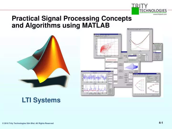
Practical Signal Processing Concepts and Algorithms using MATLAB LTI Systems
Section Outline • LTI system representations • The z-Transform • Frequency and impulse response • Introduction to filtering
Linear Time-Independent Systems x(n) y(n) δ(n) h(n)
Linear System Representations:Difference Equations >> b = [b0 b1 .. bM]; a = [a0 .. aN]; Example: >> b = [1 2 0]; a = [1 0 0.2];
The z-Transform x(n) X(z) • Linearity and superposition are preserved • x(n–k) z–kX(z) • x(–n) X(1/z) • anx(n) X(z/a) • x(n)*y(n) X(z)Y(z) y(n) = x(n)*h(n) Y(z) = X(z) H(z) Transfer function
Linear System Representations:Transfer Functions z-transform of difference equation Discrete filter form Proper form Example: >> b = [1 2 0]; >> a = [1 0 0.2];
Filters and Transfer Functions In general, the z-transform Y(z) of a digital filter's output y(n) is related to the z-transform X(z) of the input by where H(z) is the filter's transfer function. Here, the constants b(i) and a(i) are the filter coefficients and the order of the filter is the maximum of n and m. H(z)
For example let; >>step = ones(50); %input data : step function >>b = 1; % Numerator >>a = [1 -0.9]; % Denominator where the vectors b and a represent the coefficients of a filter in transfer function form. To apply this filter to your data, use >> y = filter(b,a,step); >> stem(y) >>fvtool(b,a) %GUI.Don’t have to define input (if input is %step/impulse function)%
Linear System Representations:Zero-Pole-Gain Factored proper form Zeros:z2 + 2z = 0 z(z + 2) = 0 z = 0andz = –2 Poles:z2 + 0.2 = 0 z = ± j Gain:k = 1 Example:
Zero-Pole-Gain Analysis >> b = [1 2 0]; >> a = [1 0 0.2]; >> [z,p,k] = tf2zpk(b,a); >> zplane(z,p)
Zero-Pole Placement in Filter Design x o passband stopband stable: inside unit circle minimum phase: inside unit circle x o x x o no effect on magnitude response conjugate pairs x o Steep transitions: stopband os paired with xs along same radial line Causal system: number of os ≤ number of xs
Zero-Pole-Gain Editing in SPTool • Choose Pole/Zero Editor design algorithm • View system characteristics as you edit
Impulse Response δ(n) h(n) >> impz(b,a,n,fs)
Frequency Response >> freqz(b,a,1,fs)
Frequency Responseand the Transfer Function Frequency response Unwrapped response x o x
Filter Visualization Tool • Magnitude response • Phase response • Group delay • Impulse response • Step response • Pole-zero plot • Filter coefficients >> a = [1 0 .2]; >> b = [1 2 0]; >> fvtool(b,a)
Filtering a Signal >> y = filter(b,a,x)
Filter Implementation and AnalysisConvolution and Filtering The mathematical foundation of filtering is convolution. The MATLAB conv function performs standard one-dimensional convolution, convolving one vector with another A digital filter's output y(k) is related to its input x(k) by convolution with its impulse response h(k). >> x = [1 2 1]; >> h = [1 1 1]; >> y = conv(h,x); >> stem(y)
Importing a Filter into SPTool Choose FileImport from the SPTool main menu.
Applying a Filter in SPTool Applying a Filter in SPTool Select the signal and the filter Choose the name of the output signal Click on Apply
Filter Coefficients and Filter Names In general, the z-transform Y(z) of a digital filter's output y(n) is related to the z-transform X(z) of the input by • Many standard names for filters reflect the number of a and b coefficients present: • When n=0 (that is, b is a scalar), the filter is an Infinite Impulse Response (IIR), all-pole, recursive, or autoregressive (AR) filter. • When m=0 (that is, a is a scalar), the filter is a Finite Impulse Response (FIR), all-zero, nonrecursive, or moving-average (MA) filter. • If both n and m are greater than zero, the filter is an IIR, pole-zero, recursive, or autoregressive moving-average (ARMA) filter.
IIR Filter Design • The primary advantage of IIR filters over FIR filters is that they typically meet a given set of specifications with a much lower filter order than a corresponding FIR filter.
Section Summary • LTI system representations • The z-transform • Frequency and impulse response • Introduction to filtering


![[I213 Discrete Signal Processing] MATLAB](https://cdn3.slideserve.com/6703415/slide1-dt.jpg)