Download
1 / 20
250 likes | 603 Views
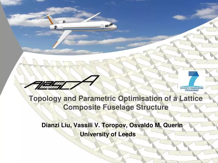
Topology and Parametric Optimisation of a Lattice Composite Fuselage Structure. Dianzi Liu, V assili V. Toropov , Osvaldo M. Querin University of Leeds. Content. Introduction Topology Optimisation Parametric Optimisation Conclusion.

E N D
Topology and Parametric Optimisation of a Lattice Composite Fuselage Structure DianziLiu, VassiliV. Toropov, Osvaldo M. Querin • University of Leeds
Content • Introduction • Topology Optimisation • Parametric Optimisation • Conclusion
Topology OptimisationMethod • Topology Optimisation is a computational means of determining the physical domain for a structure subject to applied loads and constraints. • The method used in this research is the Solid Isotropic Material with Penalization (SIMP). • It works by minimising the compliance (maximising global stiffness) of the structure by solving the following optimization problem: • for a single load case, • or by minimising the weighted compliance for multiple (N) load cases:
Topology OptimisationLoad Cases • Topology Optimisation: minimizing the compliance of the structure for 3 load cases • Load cases consist of distributed loads over the length and loads at the barrel end(shear forces, bending moments and torque) • Question: what are the appropriate weight coefficient values?
Topology OptimisationMethod for weight allocation The following strategy was used: • Do topology optimization separately for each load case, obtain the corresponding compliance values • Allocate the weights to the individual compliance components (that correspond to the individual load cases) in the same proportion • The logic behind this is as follows: if for a particular load case topology optimization produced a relatively high compliance value, then this load case is a critical one and hence it should be taken with a higher weight in the total weighted compliance optimization problem
Topology OptimisationModel and Results • Topology Optimisation Results for 3 load cases Transverse bending Bending Torsion
Topology OptimisationResults Iso view: optimizationofthebarrelforweightedcompliance
Topology OptimisationPresence of window openings • Optimization of the barrel without windows (Top) and with windows (Bottom) • Two backbones on top and bottom of the barrel • Nearly +-45° stiffening on the side panel • Result: beam structure for the barrel • Note: SIMP approach does not consider buckling
Development of the Design Concept by DLR • Reflection on the layout of the “ideal” structure from the topology optimization it in the aircraft design context • Consideration of airworthiness and manufacturing requirements • Fuselage design concept developed by DLR • High potential for weight savings achievable due to new material for stiffeners and non-rectangular skin bays • Due to large number of parameters in the obtained concept a multi-variable optimisation should be performed
Multi-parametric Optimisation • Method: the multi-parameter global approximation-based approach used to solve the optimization problem • Problem: optimize an anisogrid composite fuselage barrel with respect to weight and stability, strength, and stiffness using 7 geometric design variables, one of which is an integer variable. • Procedure: • develop a set of numerical experiments (FEA runs) where each corresponds to a different combinations of the design variables. The concept of a uniform Latin hypercube Design of Experiments (DOE) with 101 experiments (points in the variable space) was used. • FE analysis of these 101 fuselage geometries was performed • global approximations built as explicit expressions of the design variables using Genetic Programming (GP) • parametric optimisation of the fuselage barrel by a Genetic Algorithm (GA) • verification of the optimal solution by FE simulation 10
Design of Experiments • In order to generate the sampling points for approximationbuilding, a uniform DOE (optimal Latin hypercube design) is proposed. • The main principles in this approach are as follows: • The number of levels of factors (same for each factor) is equal to the number of experiments and for each level there is only one experiment; • The points of experiments are distributed as uniformly as possible in the domain of factors, which are achieved by minimizing the equation: • where Lpqis the distance between the points p and q (p≠q) in the system. Example: A 100-point DOE generated by an optimal Latin hypercube technique 11
Genetic Programming • Genetic Programming (GP) is a symbolic regression technique, it produces an analytical expression that provides the best fit of the approximation into the data from the FE runs. • Example: a approximation for the shear strain obtained from the 101 FE responses: where Z1, Z2, …, Z7 are the design variables. Indications of the quality of fit of the obtained expression into the data: 12
FEM Modeling and Simulation Automated Multiparametric Global Barrel FEA Tool: Modeling, Analysis, and Result Summary User Defined Parameters: -Geometry -Loads -Materials -Mesh seed Session file: List of Models to be Analyzed MSC Patran MSC Nastran PCL Modeling and Analysis PCL Function Post-processing PCL Function Results: Buckling Beam Strains Displacement Skin Strains Results of all analyzed models are summarized in a separate file 13
Optimisation of the Fuselage Barrel • Composite skin and stiffeners An upward gust load case at low altitude and cruise speed Undisturbed anisogrid fuselage barrel Early design stage z Qz y x 14
Variables and Constraints Wf =20mm Radius 2m h Variables: Hf tf Circumf. Helix Rib Pitch, dep. on n 2φ Wf =20mm Frame Pitch, d FuselageGeometry • Constraints: • Strength: strains in the skin and in the stiffeners • Stiffness: bending and torsional stiffness • Stability: buckling • Normalization • Normalized mass against largest mass • Margin of safety ≥0 • Strain • Stiffness • Buckling Wh=20mm th Barrel Cross Section Hh dh=8mm dh=8mm Helix Ribs Circumferential Frames 15
Results: Summary of parametric optimisation • (±45,0,45,0,-45,90)s, 14 plies, total thickness = 1.75 mm Strength Contraint Stability, Strength, and Stiffness Contraints Optimum III geometry with realistic ply layup: 502 mm 628 mm Helical ribs: tall and slender Frames: thin and small 18.94 ° 209 mm 84 mm 9.55 ° Optimum II Optimum III and Comp. Design 16
Results: Interpretation of the skin as a laminate, 14 plies 17
Results: Interpretation of the skin as a laminate, 15 plies 18
Conclusion • Multi-parameter global metamodel-based optimization was used for: • Optimization of a composite anisogrid fuselage barrel with respect to weight, stability, strength, stiffness using 7 design variables, 1 being an integer • 101-point uniform design of numerical experiments, i.e. 101 designs analysed • Automated Multiparametric Global Barrel FEA Tool generates responses • global approximations built using Genetic Programming (GP) • parametric optimization on global approximations • optimal solution verified via FE • Overall, the use of the global metamodel-based approach has allowed to solve this optimization problem with reasonable accuracy as well as provided information on the structural behavior of the anisogrid design of a composite fuselage. • There is a good correspondence of the obtained results with the analytical estimates of DLR, e.g. the angle of the optimised triangular grid cell is 9.55° whereas the DLR value is 12° 19
Thank You for your Attention 20